600-E Series Digital Baggage Scales Installation / Setup / Operation Manual Revision 2.3 June 5, 2006 2003 Triner Scale & Mfg. Co., Inc. Contents subject to change without notice. Triner Scale 8411 Hacks Cross Road Olive Branch, MS 38654-4010 (662) 890-2385 (800) 238-0152 Fax (662) 890-2386 E-mail: info@trinerscale.com Web: www.trinerscale.
TABLE OF CONTENTS Page Chapter 1: Introduction To The 600E Digital Baggage Scale ......................................................... 1-1 Chapter 2: Installation ..................................................................................................................... 2-1 2.1 Parts List ....................................................................................................................... 2-1 2.2 Scale Base Installation (Standard Style).................................
6.4 View Calibration Values (F18)....................................................................................... 6-2 6.5 Key-in Zero Calibration Value (F19) ............................................................................. 6-2 6.6 Key-in Span Calibration Value (F20) ............................................................................ 6-3 Chapter 7: 7.1 Operation.................................................................................................................
LIST OF FIGURES 1-1 1-2 1-3 1-4 2-1 2-2 2-3 2-4 2-5 2-6 2-7 2-8 2-9 2-10 2-11 2-12 2-13 2-14 3-1 3-2 3-3 5-1 6-1 7-1 7-2 B-1 B-2 B-3 B-4 B-5 Standard Style......................................................................................................................... Detail View - Standard Style ................................................................................................... Low Profile Style .......................................................................................
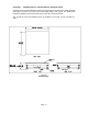
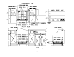
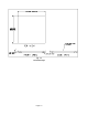
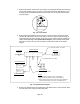
CHAPTER 1: INTRODUCTION TO THE 600E DIGITAL BAGGAGE SCALE The 600E Series of Digital Baggage Scales are general-purpose scales used to weigh baggage and freight of all sizes. They have dual remote digital displays and keypad. The displays and keypad are designed to be flush panel mounted to provide a stream lined finish. This manual will cover three different styles, the Standard, Low Profile, and the Full Well versions. Fig.
Fig.
Fig.
Fig.
CHAPTER 2: INSTALLATION 2.1 PARTS LIST PART NUMBER SC105 SSCOV SSKICK CMOD-1 FOOT02 FOOT03 DMOD-1 KMOD-1 DCBL-1 KCBL-1 WGSCR-1 WGSCR-2 WDSCR-1 WDSCR-2 ABLT-1 RCBL-1 RCBL-2 LBKT WDSCR-2 AC004 DESCRIPTION SCALE BASE STAINLESS STEEL PLATFORM COVER STAINLESS STEEL KICKPLATE SCALE CONTROL MODULE 2” DIA.
3. Remove the locknuts from the four (4) Leveling Feet. Thread the leveling feet all the way into the nuts welded in all four (4) corners of the scale lower frame (see fig. 2-2). Once the leveling feet are installed thread the locknuts back onto the top side of the leveling feet (hand tight). Fig. 2-2: Corner Detail 4. Before beginning installation into the counter it is recommended to perform an initial check of the scale system.
6. Center the frame in the bag well opening. Adjust the leveling legs so that the scale base is approximately ½” above the opening and so that the scale is in a level position. Tighten the locknuts on the leveling feet. 7. Use the Scale Anchor Holes at each corner (see fig. 2-2) to secure the scale base in place with the eight (8) wood screws provided. 8. The scale base must be grounded with the lead attached to the top frame. The center screw on an electrical outlet or a metal conduit is usually suitable.
clearly marked (see fig. 2-3 for System Block Diagram). Place stainless steel platter back onto the scale. Turn the scale on with the on/off switch located on the remote keypad. 5. Remove the stainless steel top and disconnect all cables from the control module. Place the scale base in the location provided (between ticket counters). 6. Center the frame in the opening. Adjust the leveling legs so that the scale base is in a level position. Tighten the locknuts on the leveling feet. 7.
3. Before beginning installation into the counter it is recommended to perform an initial check of the scale system. Set the scale base on the floor, level the scale and plug all components into the control module. All the ports on the control module and cables are clearly marked (see fig. 2-3 for System Block Diagram). Place stainless steel platter back onto the scale. Turn the scale on with the on/off switch located on the remote keypad. 4.
2.5 Digital Display and Keypad Installation 1. Refer to Fig. 2-7 below to cut the holes and mount the dual digital display modules into the counter. Note: Counter cut-outs to be located and cut by the customer or contractor unless otherwise specified. Fig.
Fig.
Fig. 2-9: Keypad Cut Out Detail 2. Refer to Fig. 2-9 to cut the holes and mount the keypad module into the counter. Note 1: Counter cut-outs to be located and cut by the customer or contractor unless otherwise specified. Note 2: An optional “L” Bracket is included for installations where the flush panel mount is not convenient. The “L” bracket is used for under/side counter installations.
Fig. 2-10: Keypad Cable Detail 3. Connect the display cables from the control module to each remote display (fig. 2-8). Note: Use option “A” unless there are space constraints. 4. Connect the keypad cable from the control module to the keypad module (fig. 2-10). Note: Use option “A” unless there are space constraints. 5. Connect one end of the AC adapter to the control module and the other end into a 120240 VAC grounded electrical outlet. 6.
2.6 LOADCELL CONNECTIONS Note: The scale system is pre-wired the figures below are for reference only. Color Wire Name RED BLK GRN WHT +Excitation - Excitation +Signal - Signal Figure 2-11: Color Codes for Shielded Load Cell Cable Pin Nos. 1/8 3/10 5/12 7/14 Pin Name +Excitation - Excitation +Signal 7 5 3 1 - Signal 14 12 10 8 Figure 2-12: Pin assignments for the Load Cell Port Figure 2-13: Pin assignments On Summing Card –Low Profile Style Only 2.
5 Pin No. Pin Name Signal Level 2 3 5 Receive Data Transmit Data RS-232 RS-232 Signal Ground RS-232 3 2 Front View Figure 2-14: Pin assignments for the DSUB9 serial port connector 2.8 CONNECTING THE POWER SUPPLY 1. The scale ships standard with an external AC to DC adapter. Simply plug the AC adapter into the control module’s DC Power Jack first, and then plug into a standard wall outlet (120-240 VAC).
CHAPTER 3: CONFIGURATION 3.1 CONFIGURATION OVERVIEW Note: Your scale has been configured at the factory. Do not attempt to enter the Setup Menu unless you are a trained scale technician. The scale contains two main setup menus: The Setup (“F”) menu which configures the scale to your weigh platform and the User (“A”) menu which configures the serial communication port and enables some user options. The Setup and User menus consist of several menu selections, each with its own sub-menu of choices.
PRINT ZERO LB KG ACCU SET I O Figure 3-1: Setup Menu Key Assignments F1 Grads F2 Span Gn. F3 Zero Band 0d 0.5d 1d F4 Zero Range 3d 5d F5 Mot. Band 1d 3d 5d 10d 100% 1.9% 25 50 75 100 150 200 F6 Dig. Filter F7 Ovld. Limit F8 Calib. Unit 0d 2% 1d 9d 1 2 4 8 lb kg 500 1000 1500 2000 2500 3000 4000 5000 6000 8000 10000 12000 20000 30000 40000 50000 F9 Dsp. Div. 1 2 5 F10 Dec. Pt. F16 Zero Calib. F17 Span Calib. Press ZERO key to begin Press ZERO key to begin F18 Cal.
3.3 USER (“A”) MENU 3.3.1 ENTERING THE USER MENU 1. Enter the Setup (“F”) menu by following the directions in Section 3.2.1. 2. Use the right or left directional keys shown in Figure 3-1 to move right or left in the Setup (“F”) menu until the scale shows ” A 1”. 3.3.2 NAVIGATING IN THE USER MENU Use the directional keys shown in Figure 3-1 to move around in the User Menu Chart shown in Figure 3-3 below. 1.
3.3.3 NOTES ON THE USER MENU 1. Detailed descriptions of the user menu parameters can be found in Chapter 5 of this manual. 3.3.4 EXITING THE USER MENU 1. Exit the User (“A”) menu by following the directions in Section 3.2.4. The display will go through a digit check, then settle into Normal Operating mode. All front panel keys will now return to their normal mode of operation.
CHAPTER 4: SETUP MENU DESCRIPTIONS AND PROCEDURES 4.1 SETUP MENU DESCRIPTIONS This section provides more detailed descriptions of the selections found in the Setup Menu Chart. Factory-set defaults are shown in bold with a checkmark (√). NAME/CODE DESCRIPTION CODE/VALUE F1 Graduations Specifies number of full-scale graduations. Value should be consistent with legal requirements and environmental limits on the useful system resolution. 500 F2 Span Gain Span Gain is related to A/D integration time.
NAME/CODE DESCRIPTION CODE/VALUE F9 Display Divisions Determines the desired weight increments. Value should be consistent with legal requirements. 1 2 5√ F10 Decimal Pt. Determines location of the decimal point. 0 0.00 0.0000 F16 Zero Calibration Places indicator into the zero calibration routine. Scrolling down with the ZERO key one level begins the procedure. Press ZERO key to begin sequence F17 Span Calibration Places indicator into the span calibration routine.
CHAPTER 5: USER MENU DESCRIPTIONS AND PROCEDURES 5.1 USER MENU DESCRIPTIONS This section provides more detailed descriptions of the selections found in the User Menu Chart. Factory-set defaults are shown in bold with a checkmark (√). NAME/CODE DESCRIPTION CODE/VALUE A1 Baud Rate Selects the baud rate for data transmission through the serial port. 1200 4800 A2 Data Bits and Parity Selects the number of data bits and parity of serial transmission.
A12 Bag Limit Threshold 5.2 Actuates a function that allows entry of the Bag Limit Threshold in pounds. To change the threshold use the “Print” or “Lb/Kg” key to move the flashing digit left or right. Use the “Zero” key to increment the digit. Use the “Accu” key to set the desired value. 70√ USER MENU PROCEDURES This section provides instructions for all of the User Menu procedures. 5.2.1 ID Number Entry (A8) 1.
CHAPTER 6: CALIBRATION 6.1 CALIBRATION OVERVIEW The scale is calibrated by following the procedures embedded in F16 (Zero) and F17 (Span) of the Setup Menu. Each procedure enters a value into the scale's non-volatile memory - F16 the zero value (deadweight) and F17 the span value (test weight). The minimum test weight that can be used is 1% of full-scale capacity.
4. After setting the exact value, press the ACCU key to save the value. 5. If the calibration was successful, the display will show "EndC1" momentarily, then revert back up to F17. At this time it is suggested that the calibration values be recorded for future use (see Section 6.4). 6. If the calibration was not successful, one of the error messages below will appear. Take the indicated action to correct the problem, then perform a new calibration.
6.6 KEY-IN SPAN CALIBRATION VALUE (F20) Note: This procedure is intended for emergency use only in the case of non-volatile memory loss. A valid span calibration value, obtained from a successful F17 calibration procedure, must be used. 1. While in the Setup mode, scroll to "F 20", then scroll down once using the ZERO key. 2. The display will momentarily show "CAL 1", followed by a flashing zero. Use the directional keys (shown in Figure 6-1) to adjust the displayed value to the span calibration value. 3.
CHAPTER 7: OPERATION 7.1 DISPLAY The Model 600E indicator utilizes a 6-digit LED (Light Emitting Diode) to display weight and system information. 7.1.1 LIGHT EMITTING DIODE (LED) DISPLAY Figure 7-1 shows the display detail of the 600E LED display. lb ACCU kg PCS STABLE ZERO FIGURE 7-1: 600E LED Display Detail LED Annunciator MEANING ZERO Better known as the “Center of Zero” annunciator, this light is active whenever the displayed weight is within ± 0.25 divisions of true zero.
7.2.1 FUNCTION KEYS lb/kg – This key toggles the indicator between lb and kg units if enabled in the User (“A”) Menu. See Chapter 5 for more information. Zero - This key sets the indicator to display zero and resets the bag accumulator provided the following conditions are met: 1. The displayed weight is within the zero reset range that is programmed in F4 of the Setup (“F”) Menu. 2. The scale is not in motion. 3. The scale is not in overload (see Appendix D for error codes).
APPENDIX A: SPECIFICATIONS ANALOG SPECIFICATIONS Full Scale Input Signal Minimum Sensitivity - Non H-44 Minimum Sensitivity - H-44 Input Impedance Internal Resolution Display Resolution Measurement Rate System Linearity Calibration Method Excitation Voltage 30mV, including dead load 0.4 µV / grad 1.0 µV / grad 30MΩ, typical Approximately 260,000 counts 50,000 display division max 10 Meas/sec, nominal Within 0.
APPENDIX B: SERIAL PORT INFORMATION B.1 SERIAL PORT MODES B.1.1 FULL DUPLEX MODE The Full Duplex Mode provides a Demand serial transmission mode and is selected by setting A3 to “d” and A6 to “0”. The Demand mode allows control from a host device, usually a PC, and can be activated by pressing the PRINT key on the keypad. Figure B-1 shows a suggested cable diagram for interface to a PC. Figure B-2 shows the serial data format for the Demand Mode. INDICATOR PC RXD 2 2 RXD TXD 3 3 TXD S. GND 5 5 S.
B.1.1.1 RECOGNIZED HOST COMMANDS “P” - This command is sent to the indicator to print the indicated display. The indicator will not respond if the scale is in motion, positive overload or negative overload. “Z” - This command is sent to the indicator to zero the scale. The indicator will not respond if the scale is in motion, positive overload or negative overload. The indicator will also not respond if it is not in gross mode or within the zero range specified in F4 of the Setup Menu.
B.1.3 SIMPLEX MODE The Simplex Mode provides a continuous serial transmission mode and is selected by setting A3 to “C” and A6 to “0”. The Continuous mode is used to interface to computers, scoreboards, and other remote devices requiring constant data updating. The transmission occurs at the end of each display update. Figure B-5 shows the serial data format for Continuous Mode. xxxxx.
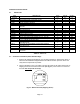
APPENDIX C: DETERMINING PROPER SPAN GAIN (F2) C.1 SPAN GAIN OVERVIEW The Span Gain parameter found in F2 of the Setup Menu is directly related to the ADC (Analog to Digital Converter) integration time. This means that the lower the setting, the higher the number of measurements per second. A span gain setting of 25 produces about 25 to 30 measurements per second, while a span gain of 200 produces only about 3 or 4 measurements per second.
# of External Grads 500 1,000 1,500 2,000 2,500 3,000 4,000 5,000 6,000 8,000 10,000 12,000 15,000 20,000 30,000 40,000 Full Scale Input Range (mV/V) 0.2 25 50 75 100 150 150 200 – – – – – – – – – 0.4 25 25 50 50 75 75 100 150 150 200 – – – – – – 0.6 25 25 25 50 50 50 75 100 100 150 200 200 – – – – 0.8 25 25 25 25 50 50 50 75 75 100 150 150 200 – – – 1.0 25 25 25 25 25 50 50 50 75 75 100 150 150 200 – – 1.2 25 25 25 25 25 25 50 50 50 75 100 100 150 200 – – 1.
APPENDIX D: DISPLAYED ERROR CODES CODE MODE MEANING / POSSIBLE SOLUTION Normal Operating Mode Gross Overload. A weight greater than the rated capacity has been applied to the scale. Remove the weight from the platter or try recalibrating the scale. Otherwise, check for a bad load cell connection or possible load cell damage due to overloading. Err 0 Span Calibration Mode (F17) Keyed-in weight value is larger than full scale capacity. Use a smaller test weight or check keyed-in value.
TRINER SCALE & MFG. CO. LIMITED WARRANTY What is Covered: Triner Scale & Mfg. Co. Inc. warrants to the first end user customer of the Triner Scale product enclosed with this limited warranty statement that the product, if purchased and used in the United States, conforms to the manufacturer’s specifications and will be free from defects in workmanship and materials for a period of one (1) year from the date of original purchase.