
User Manual

TMCM-3313 CoE Firmware Manual • Firmware Version V1.01 | Document Revision V1.02 • 2016-NOV-29
11 / 110
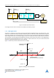
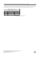
Ramp Generator
Position
Control
Velocity
Control
Torque Control
Driver
Stage
Load
Angle
Control
Field
Weakening
Current
Level
Control
Torque Control
Motor
ABN Encoder
Flags /
Status
Ramp
Parameters
Control
Parameters
velocity / position / electrical angle
velocity / position
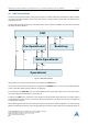
Figure 3: Closed-Loop Control Scheme
Load angle control and current level control will be executed in parallel.
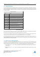
1.5.2 Load Angle Control
As typical for stepper motor drivers, phase currents will be assigned directly to he motor drivers. This
results in a current vector which should be followed by the rotor.The rotor position will be directly sampled
by encoder feedback. The closed-loop motor control monitors the resulting load angle (deviation between
driver stage current vector and encoder angle). Further on, the direction of the current vector will track the
rotor position if the load angle should impend to exceed a certain limit. The result is a load angle which
will be never exceed the given limit and as a result no step loss will occur. Thus, the current vector will
follow an overpowered load until the load is reduced.
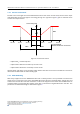
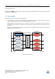
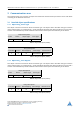
Figure 4 shows the parameters which limit the load angle.
Load Angle [µSteps]
(Deviation Current Vector and Encoder)
X_TARGET
X_TARGET - 128
128(45°) 255(90°)-128(-45°)-255(-90°)
0°
Current Vector [µSteps]
(Driver Stage)
X_TARGET - 255
X_TARGET + 128
X_TARGET + 255
2027h2027h
383(135°)-383(-135°)
Figure 4: Load Angle Control Parameter
©2016 TRINAMIC Motion Control GmbH & Co. KG, Hamburg, Germany
Terms of delivery and rights to technical change reserved.
Download newest version at www.trinamic.com
Read entire documentation.