
User Manual

TMCM-3313 CoE Firmware Manual • Firmware Version V1.01 | Document Revision V1.02 • 2016-NOV-29
10 / 110
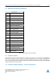
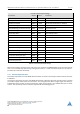
Closed-Loop Example Settings
Parameter Object Value Comment
Maximum current 2003
h
85 Set maximum motor current to 1 A
Standby current 2004
h
10 Set standby current to 0.1 A
Enocder resolution 608F
h
/1 10000 Set encoder resolution to 10000cpr
Field weakening minimim velocity 2034
h
300000 Set gamma Vmin
Field weakening maximum velocity 2035
h
1600000 Set gamma Vmax
Field weakening 2036
h
255 (default value)
Closed loop beta 2027
h
255 Beta (default value)
Current scaler minimum 2029
h
50
Current scaler maximum 202A
h
255
Maximum correction tolerance 2022
h
255
Upscale delay 2030
h
1000
Downscale delay 2031
h
10000
Correction velocity P 202B
h
3000
Correction velocity I 202C
h
20
Correction velocity I clipping 202D
h
2000
Correction velocity DV clock 202E
h
0
Correction velocity DV clipping 202F
h
100000
Correction position P 2021
h
65536
Table 2: Closed-Loop Example Settings
After these settings have been made, switch the state machine to OPERATIONAL (using the control word).
Then, turn on closed-loop operation by setting object 2020
h
to 1. Now, read object 2120
h
until its value is 1
(closed-loop initialzation finisched).
1.5.1 Closed-Loop Parameters
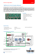
The closed-loop operation of the TMCM-3313 is based on Trinamic’s closed-loop hardware motion controller
IC TMC4361.
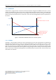
The 2-phase closed-loop control of the TMCM-3313 follows a different approach than PID control cascades
to consider stepper motor driver characteristics. The ramp generator which assigns target and velocity is
independent of the position control (commutation angle control) which is also independent of the current
control. The closed-loop control scheme is depicted in the following picture.
©2016 TRINAMIC Motion Control GmbH & Co. KG, Hamburg, Germany
Terms of delivery and rights to technical change reserved.
Download newest version at www.trinamic.com
Read entire documentation.