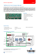
MODULE Module for Stepper Motors TMCM-3313 CoE Firmware Manual Firmware Version V1.01 | Document Revision V1.02 • 2016-NOV-29 The TMCM-3313 is a three axes controller/driver module for 2-phase bipolar stepper motors with separate differential encoder and separate home and stop switch inputs for each axis. Dynamic current control, and quiet, smooth and efficient operation are combined with stealthChop™, dcStep™, stallGuard™ and coolStep™ features.
/ 110 TMCM-3313 CoE Firmware Manual • Firmware Version V1.01 | Document Revision V1.02 • 2016-NOV-29 Contents 1 Preface 1.1 General Features of this CoE Implementation . . . 1.2 Abbreviations used in this Manual . . . . . . . . . . 1.3 Firmware Update . . . . . . . . . . . . . . . . . . . . 1.4 Trinamic’s unique Features — easy to use with CoE 1.4.1 stallGuard2 . . . . . . . . . . . . . . . . . . . 1.4.2 coolStep . . . . . . . . . . . . . . . . . . . . . 1.5 Closed-Loop Operation . . . . . . . . . . . .
/ 110 TMCM-3313 CoE Firmware Manual • Firmware Version V1.01 | Document Revision V1.02 • 2016-NOV-29 4.2.15 4.2.16 4.2.17 4.2.18 4.2.19 4.2.20 4.2.21 4.2.22 4.2.23 4.2.24 4.2.25 4.2.26 4.2.27 4.2.28 4.2.29 4.2.30 4.2.31 4.2.32 4.2.33 4.2.34 4.2.35 4.2.36 4.2.37 4.2.38 4.2.39 4.2.40 4.2.41 4.2.42 4.2.43 4.2.44 4.2.45 4.2.46 4.2.47 4.2.48 4.2.49 4.2.50 4.2.51 4.2.52 4.2.53 4.2.54 4.2.55 4.2.56 4.2.57 4.2.58 4.2.59 4.2.60 4.2.61 4.2.62 Object 2020h : Closed-loop Mode . . . . . . . . . . .
/ 110 TMCM-3313 CoE Firmware Manual • Firmware Version V1.01 | Document Revision V1.02 • 2016-NOV-29 5 Profile specific area 5.1 Detailed object specifications . . . . . . . . . . . . . . 5.1.1 Object 605Ah : Quick stop option code . . . . . 5.1.2 Object 605Bh : Shutdown option code . . . . . 5.1.3 Object 605Ch : Disable operation option code 5.1.4 Object 605Dh : Halt option code . . . . . . . . 5.1.5 Object 605Eh : Fault reaction option code . . . 5.1.6 Object 6060h : Modes of operation . . . . . . . 5.1.
/ 110 TMCM-3313 CoE Firmware Manual • Firmware Version V1.01 | Document Revision V1.02 • 2016-NOV-29 8 Homing mode 8.1 Homing Methods . . . . . . . . . . . . . . . . . . . . . . . . . . . . . . . . . . . . 8.1.1 Homing Method 1: Homing on negative Limit Switch and Index Pulse . 8.1.2 Homing Method 2: Homing on positive Limit Switch and Index Pulse . 8.1.3 Homing Method 3: Homing on positive Home Switch and Index Pulse . 8.1.4 Homing Method 5: Homing on negative Home Switch and Index Pulse 8.1.
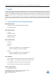
TMCM-3313 CoE Firmware Manual • Firmware Version V1.01 | Document Revision V1.02 • 2016-NOV-29 1 6 / 110 Preface This document specifies objects and modes of operation of the Triamic TMCM-3313 stepper motor control module with CANopen-over-EtherCAT (CoE) firmware. The CoE firmware is designed to fulfill the EtherCAT version of the CANopen DS402 standards. The EtherCAT conformance has also been tested.
TMCM-3313 CoE Firmware Manual • Firmware Version V1.01 | Document Revision V1.02 • 2016-NOV-29 1.
TMCM-3313 CoE Firmware Manual • Firmware Version V1.01 | Document Revision V1.02 • 2016-NOV-29 1.4.1 8 / 110 stallGuard2 stallGuard2 is a high-precision sensorless load measurement using the back EMF of the coils. It can be used for stall detection as well as other uses at loads below those which stall the motor. The stallGuard2 measurement value changes linearly over a wide range of load, velocity, and current settings. At maximum motor load, the value reaches zero or is near zero.
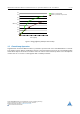
TMCM-3313 CoE Firmware Manual • Firmware Version V1.01 | Document Revision V1.02 • 2016-NOV-29 0,9 9 / 110 Efficiency with coolStep 0,8 Efficiency with 50v torque reserve 0,7 0,6 0,5 Efficiency 0,4 0,3 0,2 0,1 0 0 50 100 150 200 250 300 350 Velocity [RPM] Figure 2: Energy Efficiency Example with coolStep 1.5 Closed-Loop Operation Together with an external ABN encoder it is possible to operate each axis of the TMCM-3313 as a closedloop stepper system.
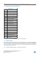
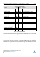
TMCM-3313 CoE Firmware Manual • Firmware Version V1.01 | Document Revision V1.02 • 2016-NOV-29 10 / 110 Closed-Loop Example Settings Parameter Object Value Comment Maximum current 2003h 85 Set maximum motor current to 1 A Standby current 2004h 10 Set standby current to 0.
/ 110 TMCM-3313 CoE Firmware Manual • Firmware Version V1.01 | Document Revision V1.02 • 2016-NOV-29 Control Parameters Ramp Parameters Flags / Status Torque Control Control Torque Ramp Generator Velocity Control Position Control Load Angle Control Current Level Control Field Weakening Driver Stage velocity / position / electrical angle Motor ABN Encoder velocity / position Figure 3: Closed-Loop Control Scheme Load angle control and current level control will be executed in parallel. 1.
TMCM-3313 CoE Firmware Manual • Firmware Version V1.01 | Document Revision V1.02 • 2016-NOV-29 1.5.3 12 / 110 Current Level Control Parallel to the load angle control the TMCM-3313 controls the motor current level (current vector amplitude) depending on the load angle to save energy during no or light load. Figure 5 gives an overview of the current control parameters. Current Value [0..
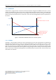
/ 110 TMCM-3313 CoE Firmware Manual • Firmware Version V1.01 | Document Revision V1.02 • 2016-NOV-29 Normal Closed Loop Load Angle [µSteps] Field Weakening max. 180° 2036h 2027h kmax. 90°N Motor Velocity [pps] 2034h 2035h Figure 6: Field Weakening • Object 2027h : Closed-loop beta. • Object 2036h : Field weakening (closed-loop gamma). • Object 2034h : Field weakening minimum velocioty (gamma Vmin). • Object 2035h : Field weakening maximum velocioty (gamma Vmax). 1.5.
TMCM-3313 CoE Firmware Manual • Firmware Version V1.01 | Document Revision V1.02 • 2016-NOV-29 2 2.1 14 / 110 Communication Reference Model The application layer comprises a concept to configure and communicate real-time-data as well as the mechanisms for synchronization between devices. The functionality which the application layer offers to an application is logically divided over different service data objects (SDO) in the application layer.
TMCM-3313 CoE Firmware Manual • Firmware Version V1.01 | Document Revision V1.02 • 2016-NOV-29 15 / 110 Service Types Type Definition Local service Involves only the local service object. The application issues a request to its local service object that executes the requested service without communicating with peer service object(s). Unconfirmed service Involves one or more peer service objects. The application issues a request to its local service object.
TMCM-3313 CoE Firmware Manual • Firmware Version V1.01 | Document Revision V1.02 • 2016-NOV-29 2.2 16 / 110 NMT State Machine The finite state machine (FSM) or simply state machine is a model of behavior composed of a finite number of states, transitions between those states, and actions. It shows which way the logic runs when certain conditions are met. Starting and resetting the device is controlled via the state machine. The NMT state machine consists of the states shown in figure 8.
/ 110 TMCM-3313 CoE Firmware Manual • Firmware Version V1.01 | Document Revision V1.02 • 2016-NOV-29 Safe-Operational state. The Bootstrap (BOOT) state is used for firmware updates via FoE. Before FoE can be used the device has to be switched to this state. 2.3 Device Model A CoE device mainly consists of the following parts: • Communication: This function unit provides the communication objects and the appropriate functionality to transport data items via the underlying network structure.
TMCM-3313 CoE Firmware Manual • Firmware Version V1.01 | Document Revision V1.02 • 2016-NOV-29 2.4 18 / 110 Object Dictionary The most important part of a device profile is the object dictionary description. The object dictionary is essentially a grouping of objects accessible via the network in an ordered pre-defined fashion. Each object within the dictionary is addressed using a 16-bit index.
TMCM-3313 CoE Firmware Manual • Firmware Version V1.01 | Document Revision V1.02 • 2016-NOV-29 19 / 110 For example, the control word for motor #1 would be 6840h (instead of 6040h for motor #0), and the microstep resolution of motor #1 would be 2200h for motor #1 (instead of 2000h for motor #0).
TMCM-3313 CoE Firmware Manual • Firmware Version V1.01 | Document Revision V1.02 • 2016-NOV-29 3 20 / 110 Communication area The communication area contains all objects that define the communication parameters of the CoE device according to the EtherCAT standard. 3.1 Detailed object specifications 3.1.1 Object 1000h : Device Type This object contains information about the device type. The object 1000h describes the type of device and its functionality.
TMCM-3313 CoE Firmware Manual • Firmware Version V1.01 | Document Revision V1.02 • 2016-NOV-29 Error Register Bits Bit Definition 0 Generic error 1 Current 2 Voltage 3 Temperature 4 Communication error 5 Device profile specific 6 Reserved (always 0) 7 Manufacturer specific Table 11: Error Register Bits 3.1.3 Object 1008h : Manufacturer Device Name This object contains the manufacturer device name.
TMCM-3313 CoE Firmware Manual • Firmware Version V1.01 | Document Revision V1.02 • 2016-NOV-29 22 / 110 Entry Description Sub-index Access PDO Mapping Value Range Default Value 0 ro no — Depends on device, e.g. 1.0. Table 15: Entry Description (1009h ) 3.1.5 Object 100Ah : Manufacturer Software Version This object contains the software version description.
/ 110 TMCM-3313 CoE Firmware Manual • Firmware Version V1.01 | Document Revision V1.02 • 2016-NOV-29 Entry Description Sub-index Description Access PDO Mapping Value Range Default Value 00h Number of entries ro no 0. . . 3 3 01h Vendor ID ro no UNSIGNED32 0286h 02h Product code ro no UNSIGNED32 3313 03h Revision number ro no UNSIGNED32 e.g. 20003h for version 2.3 Table 19: Entry Description (1018h ) 3.1.
TMCM-3313 CoE Firmware Manual • Firmware Version V1.01 | Document Revision V1.02 • 2016-NOV-29 3.1.8 24 / 110 Objects 1A00h : Transmit PDO Mapping Parameter This object contains the mapping parameters for the TPDO the device is able to transmit. The sub-index 00h contains the number of valid entries within the mapping record. This number of entries is also the number of the application variables which shall be transmitted with the corresponding TPDO.
TMCM-3313 CoE Firmware Manual • Firmware Version V1.01 | Document Revision V1.
/ 110 TMCM-3313 CoE Firmware Manual • Firmware Version V1.01 | Document Revision V1.02 • 2016-NOV-29 Entry Description Sub-index Description Access Value Range 00h Number of assigned PDOs rw 0. . . 1 01h PDO mapping index of assigned RPDO rw UNSIGNED16 Default Value 1 1600h Table 28: Entry Description (1C12h ) 3.1.11 Objects 1C13h : Sync Manager 3 PDO Assignment This object contains the index of the PDO definiton object that is assigned to sync manager 3.
TMCM-3313 CoE Firmware Manual • Firmware Version V1.01 | Document Revision V1.02 • 2016-NOV-29 4 27 / 110 Manufacturer specific area The manufacturer segment contains manufacturer specific objects. These objects control the special features of the Trinamic Motion Control device TMCM-3313. Info This section of the manual only shows the object indices for motor #0. Of course the same objects are also available for the other motors.
/ 110 TMCM-3313 CoE Firmware Manual • Firmware Version V1.01 | Document Revision V1.02 • 2016-NOV-29 coolStep™ adjustment points and thresholds Velocity Current 2003h 209Ah 20A4h 20A5h The current depends on the load of the motor. 20A6h 2003h 2003h 2004h 2004h 2004h Time 2089h coolStep area area without coolStep Current and objects Time object Velocity and objects stallGuard2 objects Figure 10: coolStep Adjustment Points and Thresholds ©2016 TRINAMIC Motion Control GmbH & Co.
TMCM-3313 CoE Firmware Manual • Firmware Version V1.01 | Document Revision V1.02 • 2016-NOV-29 29 / 110 coolStep Adjustment Objects Object Name Description 2003h Absolute maximum current The maximum value is 255. This value means 100% of the maximum current of the module. The current adjustment is within the range 0. . . 255 and can be adjusted in 32 steps (0. . . 255 divided by eight; step 0 = 0. . . 7, step 1 = 8. . . 15 and so on).
TMCM-3313 CoE Firmware Manual • Firmware Version V1.01 | Document Revision V1.02 • 2016-NOV-29 4.2 Detailed object specifications 4.2.1 Object 2000h : Microstep resolution 30 / 110 This object sets the microstep resolution of the drive. A value of 8 selects 256 (28 ) microsteps per full step.
/ 110 TMCM-3313 CoE Firmware Manual • Firmware Version V1.01 | Document Revision V1.
TMCM-3313 CoE Firmware Manual • Firmware Version V1.01 | Document Revision V1.02 • 2016-NOV-29 4.2.5 32 / 110 Object 2004h : Standby current This object defines the current used when the motor is standing (two seconds after the last move). A value of 255 means 100% of the maximum current of the drive.
TMCM-3313 CoE Firmware Manual • Firmware Version V1.01 | Document Revision V1.02 • 2016-NOV-29 33 / 110 Bit Definitions Bit Definition 0 Left limit switch deactivated, if set. 1 Right limit switch deactivated, if set. 2 Left limit switch inverted, if set. 3 Right limit switch inverted, if set. 4 Home switch deactivated, if set. 5 Home switch inverted, if set. Table 45: Bit Definitions (2005h ) 4.2.
/ 110 TMCM-3313 CoE Firmware Manual • Firmware Version V1.01 | Document Revision V1.02 • 2016-NOV-29 Entry Description Sub-index Description Access PDO Mapping Value Range Default Value 1 Null channel polarity rw no 0/1 0 2 Direction of rotation rw no 0/1 0 3 Initialize position rw no 0/1 1 Table 49: Entry Description (200Bh ) 4.2.9 Object 200Ch : Brake current feed This object configures how much current has to be fed into the brake to apply and to release it.
TMCM-3313 CoE Firmware Manual • Firmware Version V1.01 | Document Revision V1.02 • 2016-NOV-29 35 / 110 Entry Description Sub-index Access PDO Mapping Value Range Default Value 0 rw no 0. . . 268435455 0 Table 53: Entry Description (2010h ) 4.2.11 Object 2011h : Profile start acceleration This object contains the acceleration value used for ramping up from the start velocity (object 2011h , see section 4.2.10) to the velocity V1 (object (h 2012), see section 4.2.12).
TMCM-3313 CoE Firmware Manual • Firmware Version V1.01 | Document Revision V1.02 • 2016-NOV-29 4.2.13 36 / 110 Object 2013h : Profile final deceleration This object contains the deceleration value used for decelerating from the maximum positioning velocity to the velocity V1 (object 2012h , see section 4.2.12).
TMCM-3313 CoE Firmware Manual • Firmware Version V1.01 | Document Revision V1.02 • 2016-NOV-29 37 / 110 Object Description Index Name Object Type Data Type 2020h Closed-loop mode Variable UNSIGNED8 Table 62: Object Description (2020h ) Entry Description Sub-index Access PDO Mapping Value Range Default Value 0 rw no UNSIGNED8 0 Table 63: Entry Description (2020h ) 4.2.
TMCM-3313 CoE Firmware Manual • Firmware Version V1.01 | Document Revision V1.02 • 2016-NOV-29 38 / 110 Entry Description Sub-index Access PDO Mapping Value Range Default Value 0 rw no 0. . . 255 0 Table 67: Entry Description (2022h ) 4.2.18 Object 2027h : Closed-loop Beta This object sets the maximum commutation angle that can be used to compensate for an evaluated position deviation.
TMCM-3313 CoE Firmware Manual • Firmware Version V1.01 | Document Revision V1.02 • 2016-NOV-29 4.2.20 39 / 110 Object 2029h : Current Scaler Minimum Minimum current setting for current regulation in closed-loop operation. Object Description Index Name Object Type Data Type 2029h Current scaler minimum Variable UNSIGNED8 Table 72: Object Description (2029h ) Entry Description Sub-index Access PDO Mapping Value Range Default Value 0 rw no 0. . .
TMCM-3313 CoE Firmware Manual • Firmware Version V1.01 | Document Revision V1.02 • 2016-NOV-29 40 / 110 Entry Description Sub-index Access PDO Mapping Value Range Default Value 0 rw no 0. . . 16777215 — Table 77: Entry Description (202Bh ) 4.2.23 Object 202Ch : Correction Velocity I This object defines the I parameter of the PI regulator which controls the maximum velocity during closedloop regulation.
TMCM-3313 CoE Firmware Manual • Firmware Version V1.01 | Document Revision V1.02 • 2016-NOV-29 4.2.25 41 / 110 Object 202Eh : Correction Velocity DV Clock This object defines the clock divider for the D part calculation of the regulator that controls the velocity during closed-loop regulation.
TMCM-3313 CoE Firmware Manual • Firmware Version V1.01 | Document Revision V1.02 • 2016-NOV-29 42 / 110 Entry Description Sub-index Access PDO Mapping Value Range Default Value 0 rw no 0. . . 16777215 — Table 87: Entry Description (2030h ) 4.2.28 Object 2031h : Downscale Delay Delay used when decreasing the motor current during closed-loop operation.
TMCM-3313 CoE Firmware Manual • Firmware Version V1.01 | Document Revision V1.02 • 2016-NOV-29 43 / 110 Object Description Index Name Object Type Data Type 2034h Filed weakening minimum velocity Variable UNSIGNED32 Table 92: Object Description (2034h ) Entry Description Sub-index Access PDO Mapping Value Range Default Value 0 rw no 0. . . 16777215 — Table 93: Entry Description (2034h ) 4.2.31 Object 2035h : Field Weakening Maximum Velocity Maximum speed for field weakening operation.
TMCM-3313 CoE Firmware Manual • Firmware Version V1.01 | Document Revision V1.02 • 2016-NOV-29 44 / 110 Entry Description Sub-index Access PDO Mapping Value Range Default Value 0 rw no 0. . . 255 — Table 97: Entry Description (2036h ) 4.2.33 Object 204Eh : Boost Current This object defines the motor current that will be used during the acceleration phase and the deceleration phase in open-loop mode. A value of 255 means 100% of the maximum motor current of the drive.
TMCM-3313 CoE Firmware Manual • Firmware Version V1.01 | Document Revision V1.02 • 2016-NOV-29 4.2.35 45 / 110 Object 208Ch : Velocity Dimension Index With this object different units can be chosen: • Writing 0 selects internal units. • Writing 181 sets PPS for velocity and PPS/s for acceleration. This can only be changed in SWITCHED_ON_DISABLED mode.
TMCM-3313 CoE Firmware Manual • Firmware Version V1.01 | Document Revision V1.02 • 2016-NOV-29 46 / 110 Object Description Index Name Object Type Data Type 2092h Chopper Blank Time Variable UNSIGNED8 Table 106: Object Description (2092h ) Entry Description Sub-index Access PDO Mapping Value Range Default Value 0 rw no 0. . . 3 2 Table 107: Entry Description (2092h ) 4.2.
TMCM-3313 CoE Firmware Manual • Firmware Version V1.01 | Document Revision V1.02 • 2016-NOV-29 47 / 110 Entry Description Sub-index Access PDO Mapping Value Range Default Value 0 rw no 0. . . 3 0 Table 111: Entry Description (2094h ) 4.2.40 Object 2095h : Chopper Hysteresis End This object provides the setting of the hysteresis end value after a number of decrements. The decrement interval time is controlled by object 2094h (section 4.2.39). Possible values are: • -3. . .
TMCM-3313 CoE Firmware Manual • Firmware Version V1.01 | Document Revision V1.02 • 2016-NOV-29 48 / 110 Entry Description Sub-index Access PDO Mapping Value Range Default Value 0 rw no 0. . . 8 3 Table 115: Entry Description (2096h ) 4.2.42 Object 2097h : Chopper Off Time The off time setting controls the minimum chopper frequency. Under normal circumstances, an off time within the range of 5µs to 20µs is used. Off time setting for constant tOFF chopper: NCLK = 12 + 32 ∗ tOF F .
TMCM-3313 CoE Firmware Manual • Firmware Version V1.01 | Document Revision V1.02 • 2016-NOV-29 49 / 110 Entry Description Sub-index Access PDO Mapping Value Range Default Value 0 rw no 0/1 0 Table 119: Entry Description (2098h ) 4.2.44 Object 2099h : Smart Energy Current Down Step This object provides the setting of the number of stallGuard2 readings above the upper threshold necessary for each current decrement of the motor current.
TMCM-3313 CoE Firmware Manual • Firmware Version V1.01 | Document Revision V1.02 • 2016-NOV-29 50 / 110 Entry Description Sub-index Access PDO Mapping Value Range Default Value 0 rw no 0. . . 15 0 Table 123: Entry Description (209Ah ) 4.2.46 Object 209Bh : Smart Energy Current Up Step This object sets the current increment step. The current becomes incremented for each measured stallGuard2 value below the lower threshold (see smart energy hysteresis start (object 209Ch , section 4.2.47).
TMCM-3313 CoE Firmware Manual • Firmware Version V1.01 | Document Revision V1.02 • 2016-NOV-29 51 / 110 Entry Description Sub-index Access PDO Mapping Value Range Default Value 0 rw no 0. . . 15 0 Table 127: Entry Description (209Ch ) 4.2.48 Object 209Dh : Smart Energy Filter Enable This object is used to set the stallGuard2 filter for more precision of the measurement. It reduces the measurement frequency to one measurement per four fullsteps if set.
TMCM-3313 CoE Firmware Manual • Firmware Version V1.01 | Document Revision V1.02 • 2016-NOV-29 52 / 110 Entry Description Sub-index Access PDO Mapping Value Range Default Value 0 rw no -63. . . 63 0 Table 131: Entry Description (209Eh ) 4.2.50 Object 20A1h : Short Protection Disable This object is used to enable or to disable the short to ground protection. Normally there is no need to change this. Use the default value.
TMCM-3313 CoE Firmware Manual • Firmware Version V1.01 | Document Revision V1.02 • 2016-NOV-29 53 / 110 Entry Description Sub-index Access PDO Mapping Value Range Default Value 0 rw no 0/1 0 Table 135: Entry Description (20A3h ) 4.2.52 Object 20A4h : Stop on Stall Below this speed the motor will not be stopped. Above this speed the motor will be stopped in case the stallGuard2 load value reaches zero.
TMCM-3313 CoE Firmware Manual • Firmware Version V1.01 | Document Revision V1.02 • 2016-NOV-29 4.2.54 Object 2100h : Home Offset Display This object shows the home offset. The value is given in microsteps. Object Description Index Name Object Type Data Type 2100h Home Offset Display Variable SIGNED32 Table 140: Object Description (2100h ) Entry Description Sub-index Access PDO Mapping Value Range Default Value 0 ro no -2147483648. . .
TMCM-3313 CoE Firmware Manual • Firmware Version V1.01 | Document Revision V1.
TMCM-3313 CoE Firmware Manual • Firmware Version V1.01 | Document Revision V1.02 • 2016-NOV-29 56 / 110 Entry Description Sub-index Access PDO Mapping Value Range Default Value 0 ro no 0. . . 8 8 Table 148: Entry Description (2107h ) 4.2.58 Object 210Bh : Step Counter This object shows the overall number of microsteps done by this motor so far. The value can be read as a 64 bit value (sub-index 3) or split into two 32 bit values (sub-index 1 and sub-index 2).
TMCM-3313 CoE Firmware Manual • Firmware Version V1.01 | Document Revision V1.02 • 2016-NOV-29 4.2.60 57 / 110 Object 2702h : Device Digital Inputs Bits 23. . . 16 of this object reflect the states of the general purpose inputs of the module. The number of available inputs depends on the module type.
TMCM-3313 CoE Firmware Manual • Firmware Version V1.01 | Document Revision V1.02 • 2016-NOV-29 Object Description Index Name Object Type Data Type 2703h Device Digital Outputs Variable ARRAY Table 157: Object Description (2703h ) Entry Description Sub-index Description Access PDO Mapping Value Range Default Value 1 Physical outputs rw yes UNSIGNED32 0 2 Output mask rw yes UNSIGNED32 0 Table 158: Entry Description (2703h ) 4.2.
TMCM-3313 CoE Firmware Manual • Firmware Version V1.01 | Document Revision V1.02 • 2016-NOV-29 5 59 / 110 Profile specific area The profile segment contains CiA-402 standard motion control objects. These objects control the motion control functions of the TMCM-3313. Since it is not possible to operate the modes in parallel, the user is able to activate the required function by selecting a mode of operation. The control device writes to the modes of operation object in order to select the operation mode.
TMCM-3313 CoE Firmware Manual • Firmware Version V1.01 | Document Revision V1.
TMCM-3313 CoE Firmware Manual • Firmware Version V1.01 | Document Revision V1.02 • 2016-NOV-29 61 / 110 Entry Description Sub-index Access PDO Mapping Value Range Default Value 0 rw no 0 0 Table 167: Entry Description (605Bh ) 5.1.3 Object 605Ch : Disable operation option code This object indicates what action is performed if there is a transition from operation enabled state to switched on state. The disable operation option code always has the value 1 as only this is supported.
TMCM-3313 CoE Firmware Manual • Firmware Version V1.01 | Document Revision V1.02 • 2016-NOV-29 62 / 110 Object Description Index Name Object Type Data Type 605Dh Halt option code Variable UNSIGNED16 Table 172: Object Description (605Dh ) Entry Description Sub-index Access PDO Mapping Value Range Default Value 0 rw no 1 1 Table 173: Entry Description (605Dh ) 5.1.
TMCM-3313 CoE Firmware Manual • Firmware Version V1.01 | Document Revision V1.02 • 2016-NOV-29 63 / 110 Value Definition Value Mode 0 No mode 1 Profile position mode (pp) 3 Profile velocity mode (pv) 6 Homing mode (hm) Table 177: Value Description (6060h ) The motor will not run when the operating mode is set to 0. It will be stopped when the motor is running in one of the supported operating modes and the operating mode is then switched to 0.
TMCM-3313 CoE Firmware Manual • Firmware Version V1.01 | Document Revision V1.02 • 2016-NOV-29 64 / 110 Object Description Index Name Object Type Data Type 6061h Modes of operation display Variable SIGNED8 Table 181: Object Description (6061h ) Entry Description Sub-index Access PDO Mapping Value Range Default Value 0 rw refer to CiA-402 0/1/3/6 0 Table 182: Entry Description (6061h ) 5.1.
TMCM-3313 CoE Firmware Manual • Firmware Version V1.01 | Document Revision V1.02 • 2016-NOV-29 65 / 110 All values are dimensionless. Object Description Index Name Object Type Data Type 608Fh Position Encoder Resolution Array UNSIGNED32 Table 186: Object Description (608Fh ) Entry Description Sub-index Description Access PDO Mapping Value Range Default Value 0 Highest sub-index supported ro no 2 2 1 Encoder increments rw no 0. . .
TMCM-3313 CoE Firmware Manual • Firmware Version V1.01 | Document Revision V1.
TMCM-3313 CoE Firmware Manual • Firmware Version V1.01 | Document Revision V1.02 • 2016-NOV-29 6 67 / 110 Profile position mode A target position is applied to the trajectory generator. It is generating a position demand value for the position control loop described in the position control function. Please refer to object 6060h (section 5.1.6) for information about how to choose an operation mode. Object 6061h (section 5.1.7) shows the operation mode that is set. 6.
TMCM-3313 CoE Firmware Manual • Firmware Version V1.01 | Document Revision V1.02 • 2016-NOV-29 6.1.1 68 / 110 Object 6040h : Control Word This object indicates the received command controlling the power drive system finite state automaton (PDS FSA). The CiA-402 state machine can be controlled using this object. Please refer to figure 12 for detailed information.
/ 110 TMCM-3313 CoE Firmware Manual • Firmware Version V1.01 | Document Revision V1.02 • 2016-NOV-29 Object Description Index Name Object Type Data Type 6040h Controlword Variable UNSIGNED16 Table 196: Object Description (6040h in pp Mode) Entry Description Sub-index Access PDO Mapping Value Range Default Value 0 rw see CiA402-3 See command coding above. Table 197: Entry Description (6040h in pp Mode) 6.1.2 Object 6041h : Status Word This object provides the status of the PDS FSA.
TMCM-3313 CoE Firmware Manual • Firmware Version V1.01 | Document Revision V1.02 • 2016-NOV-29 70 / 110 Operation Mode specific Bits in pp Mode Bit Name Definition 10 Target reached Set when the motor is within the position window. 12 Set point acknowledged 0: Set point processed. 1: Set point still in process. 13 Following error Not supported.
TMCM-3313 CoE Firmware Manual • Firmware Version V1.01 | Document Revision V1.02 • 2016-NOV-29 71 / 110 Object Description Index Name Object Type Data Type 6062h Position Demand Value Variable SIGNED32 Table 204: Object Description (6062h ) Entry Description Sub-index Access PDO Mapping Value Range Default Value 0 ro Refer to CiA402-3 SIGNED32 no Table 205: Entry Description (6062h ) 6.1.
TMCM-3313 CoE Firmware Manual • Firmware Version V1.01 | Document Revision V1.02 • 2016-NOV-29 72 / 110 Entry Description Sub-index Access PDO Mapping Value Range Default Value 0 ro Refer to CiA402-3 SIGNED32 no Table 209: Entry Description (6064h ) 6.1.6 Object 6065h : Following Error Window This object indicates the configured range of tolerated position values symmetrically to the position demand value.
TMCM-3313 CoE Firmware Manual • Firmware Version V1.01 | Document Revision V1.02 • 2016-NOV-29 73 / 110 Object Description Index Name Object Type Data Type 6067h Position Window Variable UNSIGNED32 Table 212: Object Description (6067h ) Entry Description Sub-index Access PDO Mapping Value Range Default Value 0 rw no UNSIGNED32 FFFFFFFFh Table 213: Entry Description (6067h ) 6.1.
TMCM-3313 CoE Firmware Manual • Firmware Version V1.01 | Document Revision V1.02 • 2016-NOV-29 74 / 110 Entry Description Sub-index Access PDO Mapping Value Range Default Value 0 ro Refer to CiA402-3 SIGNED32 no Table 217: Entry Description (606Ch ) 6.1.
TMCM-3313 CoE Firmware Manual • Firmware Version V1.01 | Document Revision V1.02 • 2016-NOV-29 75 / 110 Entry Description Sub-index Description Access PDO Mapping Value Range Default Value 1 Mininmum Position Limit rw no SIGNED32 -2147483648 2 Maximum Position Limit rw no SIGNED32 2147483647 Table 221: Entry Description (607Dh ) 6.1.
TMCM-3313 CoE Firmware Manual • Firmware Version V1.01 | Document Revision V1.02 • 2016-NOV-29 6.1.14 76 / 110 Object 6083h : Profile Acceleration This object indicates the configured acceleration. Object 6083h sets the maximum acceleration to be used in profile positioning and in profile velocity mode. The units for object 6083h can be choosen with object 208Eh , described in section 4.2.36.
TMCM-3313 CoE Firmware Manual • Firmware Version V1.01 | Document Revision V1.02 • 2016-NOV-29 77 / 110 Object Description Index Name Object Type Data Type 6085h Quick stop deceleration Variable UNSIGNED32 Table 230: Object Description (6085h ) Entry Description Sub-index Access PDO Mapping Value Range Default Value 0 rw no UNSIGNED32 51200 Table 231: Entry Description (6085h ) 6.1.
/ 110 TMCM-3313 CoE Firmware Manual • Firmware Version V1.01 | Document Revision V1.02 • 2016-NOV-29 Object Description Index Name Object Type Data Type 60A4h Profile Jerk Array UNSIGNED32 Table 235: Object Description (60A4h ) Entry Description Sub-index Description Access PDO Mapping Value Range Default Value 0 Highest sub-index supported ro no 4 4 1 Profile jerk 1 rw no 0. . . 16777215 0 2 Profile jerk 2 rw no 0. . . 16777215 0 3 Profile jerk 3 rw no 0. . .
TMCM-3313 CoE Firmware Manual • Firmware Version V1.01 | Document Revision V1.02 • 2016-NOV-29 79 / 110 Entry Description Sub-index Access PDO Mapping Value Range Default Value 0 rw no UNSIGNED16 0 Table 239: Entry Description (60F2h ) 6.2 How to move a Motor in pp Mode Here is a little example that shows how to get a motor running in pp mode. In this little example we assume that the module has been reset (and then switched to pre-operational or operational) by NMT commands before.
TMCM-3313 CoE Firmware Manual • Firmware Version V1.01 | Document Revision V1.02 • 2016-NOV-29 7 80 / 110 Profile velocity mode The profile velocity mode is used to control the velocity of the drive without a special regard of the position. It contains limit functions and trajectory generation. The profile velocity mode covers the following sub-functions: • Demand value input via trajectory generator. • Monitoring of the profile velocity using a window-function.
/ 110 TMCM-3313 CoE Firmware Manual • Firmware Version V1.01 | Document Revision V1.
TMCM-3313 CoE Firmware Manual • Firmware Version V1.01 | Document Revision V1.02 • 2016-NOV-29 Trinamic Specific Bits Bit Name Definition 14 Motor activity 0: Motor stands still. 1: Motor rotates. 15 Direction of rotation This bit shows the direction of rotation. Table 245: Trinamic Specific Bits Operation Mode specific Bits in pv Mode Bit Name Definition 10 Target reached Indicates that the target speed has been reached. 12 Speed Not supported. 13 Max. slippage error Not supported.
TMCM-3313 CoE Firmware Manual • Firmware Version V1.01 | Document Revision V1.02 • 2016-NOV-29 83 / 110 Entry Description Sub-index Access PDO Mapping Value Range Default Value 0 rw see CiA402-3 See state coding above Table 249: Entry Description (6041h in pv Mode) 7.1.3 Object 6062h : Position Demand Value This object provides the demanded position value. The value is given in microsteps. Object 6062h indicates the actual position that the motor should have.
TMCM-3313 CoE Firmware Manual • Firmware Version V1.01 | Document Revision V1.02 • 2016-NOV-29 7.1.5 84 / 110 Object 6064h : Position Actual Value This object provides the actual value of the position measurement device. It always contains the same value as object 6063h .
TMCM-3313 CoE Firmware Manual • Firmware Version V1.01 | Document Revision V1.02 • 2016-NOV-29 7.1.7 85 / 110 Object 606Ch : Velocity Actual Value This object shows the actual velocity value of the motor. The value is given in internal or user-defined velocity units (depending on object 208Ch , described in section 4.2.35).
TMCM-3313 CoE Firmware Manual • Firmware Version V1.01 | Document Revision V1.02 • 2016-NOV-29 7.1.9 86 / 110 Object 6083h : Profile Acceleration This object indicates the configured acceleration. Object 6083h sets the maximum acceleration to be used in profile positioning and in profile velocity mode. The units for object 6083h can be choosen with object 208Eh , described in section 4.2.36.
TMCM-3313 CoE Firmware Manual • Firmware Version V1.01 | Document Revision V1.02 • 2016-NOV-29 87 / 110 Object Description Index Name Object Type Data Type 6085h Quick stop deceleration Variable UNSIGNED32 Table 266: Object Description (6085h ) Entry Description Sub-index Access PDO Mapping Value Range Default Value 0 rw no UNSIGNED32 51200 Table 267: Entry Description (6085h ) 7.1.
/ 110 TMCM-3313 CoE Firmware Manual • Firmware Version V1.01 | Document Revision V1.02 • 2016-NOV-29 Object Description Index Name Object Type Data Type 60A4h Profile Jerk Array UNSIGNED32 Table 271: Object Description (60A4h ) Entry Description Sub-index Description Access PDO Mapping Value Range Default Value 0 Highest sub-index supported ro no 4 4 1 Profile jerk 1 rw no 0. . . 16777215 0 2 Profile jerk 2 rw no 0. . . 16777215 0 3 Profile jerk 3 rw no 0. . .
TMCM-3313 CoE Firmware Manual • Firmware Version V1.01 | Document Revision V1.02 • 2016-NOV-29 89 / 110 • Select pv mode by writing 3 to object 6060h . • Write 6 to object 6040h to switch to READY_TO_SWITCH_ON state. • Write 7 to object 6040h to switch to SWITCHED_ON state. • Write 15 to object 6040h to switch to OPERATION_ENABLED state. • Write the desired target speed (e.g. 100000) to object 60FFh . The motor now accelerates to that speed. • Stop the motor by writing 0 to object 60FFh .
TMCM-3313 CoE Firmware Manual • Firmware Version V1.01 | Document Revision V1.02 • 2016-NOV-29 8 90 / 110 Homing mode This chapter describes the method by which a drive seeks the home position (reference point). There are various methods of achieving this using limit switches at the ends of travel or a home switch in mid-travel. Some methods also use the index (zero) pulse train from an incremental encoder. The user may specify the speeds, acceleration and the method of homing.
TMCM-3313 CoE Firmware Manual • Firmware Version V1.01 | Document Revision V1.02 • 2016-NOV-29 8.1 91 / 110 Homing Methods The TMCM-3313 supports a subset of different standard CANopen homing methods. The homing method that is to be used can be choosen via object 6098h (section 8.2.5). Supported Homing Methods Method Description 0 No homing (default value for object 6098h ). 1 Search the left end switch, then search the next encoder index pulse.
TMCM-3313 CoE Firmware Manual • Firmware Version V1.01 | Document Revision V1.02 • 2016-NOV-29 8.1.2 92 / 110 Homing Method 2: Homing on positive Limit Switch and Index Pulse Using this method, the initial direction of movement shall be rightward if the positive limit switch is inactive (here: low). The position of home shall be at the first index pulse to the left of the position where the positive limit switch becomes inactive. 2 2 Index pulse Positive limit switch Figure 15: Homing Method 2 8.1.
TMCM-3313 CoE Firmware Manual • Firmware Version V1.01 | Document Revision V1.02 • 2016-NOV-29 93 / 110 5 5 Index pulse Home switch Figure 17: Homing Method 5 8.1.5 Homing Method 17, 18, 19, and 21: Homing without Index Pulse These methods are similar to methods 1 to 5 except that the home position is not dependent on the index pulse but only dependent on the relevant home or limit switch transitions. As an example, homing method 19 (which is similar to homing method 3) is shown in figure 18.
TMCM-3313 CoE Firmware Manual • Firmware Version V1.01 | Document Revision V1.02 • 2016-NOV-29 94 / 110 33 34 Index pulse Figure 19: Homing Methods 33 and 34 8.1.7 Homing Method 35: Current position as home position In this method, the current position shall be taken to be the home position. This method does not require the drive device to be in operation enabled state. ©2016 TRINAMIC Motion Control GmbH & Co. KG, Hamburg, Germany Terms of delivery and rights to technical change reserved.
TMCM-3313 CoE Firmware Manual • Firmware Version V1.01 | Document Revision V1.02 • 2016-NOV-29 8.2 8.2.1 95 / 110 Detailed Object Specifications Object 6040h : Control Word This object indicates the received command controlling the power drive system finite state automaton (PDS FSA). The CiA-402 state machine can be controlled using this object. Please refer to figure 12 for detailed information.
/ 110 TMCM-3313 CoE Firmware Manual • Firmware Version V1.01 | Document Revision V1.02 • 2016-NOV-29 Object Description Index Name Object Type Data Type 6040h Controlword Variable UNSIGNED16 Table 280: Object Description (6040h in hm Mode) Entry Description Sub-index Access PDO Mapping Value Range Default Value 0 rw see CiA402-3 See command coding above. Table 281: Entry Description (6040h in hm Mode) 8.2.2 Object 6041h : Status Word This object provides the status of the PDS FSA.
TMCM-3313 CoE Firmware Manual • Firmware Version V1.01 | Document Revision V1.02 • 2016-NOV-29 97 / 110 Operation Mode specific Bits in hm Mode Bit Name Definition 10 Target reached Set when the zero position has been found or homing has been stopped by setting controlword bit 4 to zero. 12 Home attained Set when zero position has been found. 13 Homing error Not supported.
TMCM-3313 CoE Firmware Manual • Firmware Version V1.01 | Document Revision V1.02 • 2016-NOV-29 98 / 110 Object Description Index Name Object Type Data Type 606Ch Velocity Actual Value Variable SIGNED32 Table 288: Object Description (606Ch ) Entry Description Sub-index Access PDO Mapping Value Range Default Value 0 ro Refer to CiA402-3 SIGNED32 no Table 289: Entry Description (606Ch ) 8.2.
/ 110 TMCM-3313 CoE Firmware Manual • Firmware Version V1.01 | Document Revision V1.02 • 2016-NOV-29 8.2.5 Object 6098h : Homing Method The homing method to be used can be selected by writing to this object. Please see table 275 for a list of homing methods supported by the current version of the TMCM-3313 CANopen firmware.
TMCM-3313 CoE Firmware Manual • Firmware Version V1.01 | Document Revision V1.02 • 2016-NOV-29 100 / 110 Object Description Index Name Object Type Data Type 609Ah Homing acceleration Variable UNSIGNED32 Table 296: Object Description (609Ah ) Entry Description Sub-index Access PDO Mapping Value Range Default Value 0 rw no UNSIGNED32 0 Table 297: Entry Description (609Ah ) 8.2.8 Object 2100h : Home Offset Display This object shows the home offset. The value is given in microsteps.
TMCM-3313 CoE Firmware Manual • Firmware Version V1.01 | Document Revision V1.02 • 2016-NOV-29 • Write 31 to object 6040h to start the homing process. • Press and release the home switch. • When homing has finished, write 15 to object 6040h again. ©2016 TRINAMIC Motion Control GmbH & Co. KG, Hamburg, Germany Terms of delivery and rights to technical change reserved. Download newest version at www.trinamic.com Read entire documentation.
TMCM-3313 CoE Firmware Manual • Firmware Version V1.01 | Document Revision V1.02 • 2016-NOV-29 9 102 / 110 Emergency Messages (EMCY) The module sends an emergency message if an error occurs. The message contains information about the error type. The module can map internal errors and object 1001h (error register) is part of every emergency object. Please note that the additional byte #2 shows which motor is affected.
TMCM-3313 CoE Firmware Manual • Firmware Version V1.01 | Document Revision V1.02 • 2016-NOV-29 Error code Additional byte 103 / 110 Description 1 2 3 4 5 8611h 0 0. . . 2 0 0 0 Following error The deviation between motor position counter and encoder position counter has exceeded the following error window. ff00h 0 0. . . 2 0 0 0 Undervoltage The supply voltage is too low to drive a motor. ff01h 1 0. . .
/ 110 TMCM-3313 CoE Firmware Manual • Firmware Version V1.01 | Document Revision V1.02 • 2016-NOV-29 10 1 2 3 4 5 6 7 8 9 10 Figures Index stallGuard2 Load Measurement as a Function of Load . . . . . . . . . . . . Energy Efficiency Example with coolStep Closed-Loop Control Scheme . . . . . Load Angle Control Parameter . . . . Current Level Control . . . . . . . . . . Field Weakening . . . . . . . . . . . . . Position Catch up . . . . . . . . . . . . NMT State Machine . . . . . . . . . . .
/ 110 TMCM-3313 CoE Firmware Manual • Firmware Version V1.01 | Document Revision V1.02 • 2016-NOV-29 11 1 2 3 4 5 6 7 8 9 10 11 12 13 14 15 16 17 18 19 20 21 22 23 24 25 26 27 28 29 30 31 32 33 34 35 36 37 38 39 40 41 42 43 44 45 46 47 48 49 50 51 Tables Index Abbreviations used in this Manual . . Closed-Loop Example Settings . . . . Service Primitives . . . . . . . . . . . . Service Types . . . . . . . . . . . . . . Object Dictionary . . . . . . . . . . . . Multi-Axis Object Indices . . . . . . . .
TMCM-3313 CoE Firmware Manual • Firmware Version V1.01 | Document Revision V1.02 • 2016-NOV-29 104 105 106 107 108 109 110 111 112 113 114 115 116 117 118 119 120 121 122 123 124 125 126 127 128 129 130 131 132 133 134 135 136 137 138 139 140 141 142 143 144 145 146 147 148 149 150 151 152 153 154 155 156 157 Object Description (208Eh ) . Entry Description (208Eh ) . Object Description (2092h ) . Entry Description (2092h ) . Object Description (2093h ) . Entry Description (2093h ) .
TMCM-3313 CoE Firmware Manual • Firmware Version V1.01 | Document Revision V1.02 • 2016-NOV-29 210 211 212 213 214 215 216 217 218 219 220 221 222 223 224 225 226 227 228 229 230 231 232 233 234 235 236 237 238 239 240 241 242 243 244 245 246 247 248 249 250 251 252 253 254 255 256 257 Object Description (6065h ) . . . . . . . Entry Description (6065h ) . . . . . . . Object Description (6067h ) . . . . . . . Entry Description (6067h ) . . . . . . . Object Description (6068h ) . . . . . . .
TMCM-3313 CoE Firmware Manual • Firmware Version V1.01 | Document Revision V1.02 • 2016-NOV-29 12 108 / 110 Supplemental Directives 12.1 Producer Information 12.2 Copyright TRINAMIC owns the content of this user manual in its entirety, including but not limited to pictures, logos, trademarks, and resources. © Copyright 2016 TRINAMIC. All rights reserved. Electronically published by TRINAMIC, Germany.
TMCM-3313 CoE Firmware Manual • Firmware Version V1.01 | Document Revision V1.02 • 2016-NOV-29 109 / 110 or of any other nature are made hereunder with respect to information/specification or the products to which information refers and no guarantee with respect to compliance to the intended use is given. In particular, this also applies to the stated possible applications or areas of applications of the product.
TMCM-3313 CoE Firmware Manual • Firmware Version V1.01 | Document Revision V1.02 • 2016-NOV-29 13 Revision History 13.1 Firmware Revision Version Date Author Description 1.01 2016-JUL-20 OK First release. Table 301: Firmware Revision 13.2 Document Revision Version Date Author Description V1.01 2016-JUL-20 OK First release. V1.02 2016-NOV-29 OK Block diagrams included. Table 302: Document Revision ©2016 TRINAMIC Motion Control GmbH & Co.