
User Manual


Table Of Contents
- 1 Features
- 2 First Steps with TMCL
- 3 TMCL and the TMCL-IDE — An Introduction
- 3.1 Binary Command Format
- 3.2 Reply Format
- 3.3 Standalone Applications
- 3.4 TMCL Command Overview
- 3.5 TMCL Commands by Subject
- 3.6 Detailed TMCL Command Descriptions
- 3.6.1 ROR (Rotate Right)
- 3.6.2 ROL (Rotate Left)
- 3.6.3 MST (Motor Stop)
- 3.6.4 MVP (Move to Position)
- 3.6.5 SAP (Set Axis Parameter)
- 3.6.6 GAP (Get Axis Parameter)
- 3.6.7 SGP (Set Global Parameter)
- 3.6.8 GGP (Get Global Parameter)
- 3.6.9 STGP (Store Global Parameter)
- 3.6.10 RSGP (Restore Global Parameter)
- 3.6.11 RFS (Reference Search)
- 3.6.12 SIO (Set Output)
- 3.6.13 GIO (Get Input)
- 3.6.14 CALC (Calculate)
- 3.6.15 COMP (Compare)
- 3.6.16 JC (Jump conditional)
- 3.6.17 JA (Jump always)
- 3.6.18 CSUB (Call Subroutine)
- 3.6.19 RSUB (Return from Subroutine)
- 3.6.20 WAIT (Wait for an Event to occur)
- 3.6.21 STOP (Stop TMCL Program Execution – End of TMCL Program)
- 3.6.22 SCO (Set Coordinate)
- 3.6.23 GCO (Get Coordinate)
- 3.6.24 CCO (Capture Coordinate)
- 3.6.25 ACO (Accu to Coordinate)
- 3.6.26 CALCX (Calculate using the X Register)
- 3.6.27 AAP (Accu to Axis Parameter)
- 3.6.28 AGP (Accu to Global Parameter)
- 3.6.29 CLE (Clear Error Flags)
- 3.6.30 EI (Enable Interrupt)
- 3.6.31 DI (Disable Interrupt)
- 3.6.32 VECT (Define Interrupt Vector)
- 3.6.33 RETI (Return from Interrupt)
- 3.6.34 Customer specific Command Extensions (UF0…UF7 – User Functions)
- 3.6.35 Request Target Position reached Event
- 3.6.36 TMCL Control Commands
- 4 Axis Parameters
- 5 Global Parameters
- 6 Hints and Tips
- 7 TMCL Programming Techniques and Structure
- 8 Figures Index
- 9 Tables Index
- 10 Supplemental Directives
- 11 Revision History
TMCM-3212 TMCL
™
Firmware Manual • Firmware Version V1.07 | Document Revision V1.04 • 2017-JUN-08
92 / 103
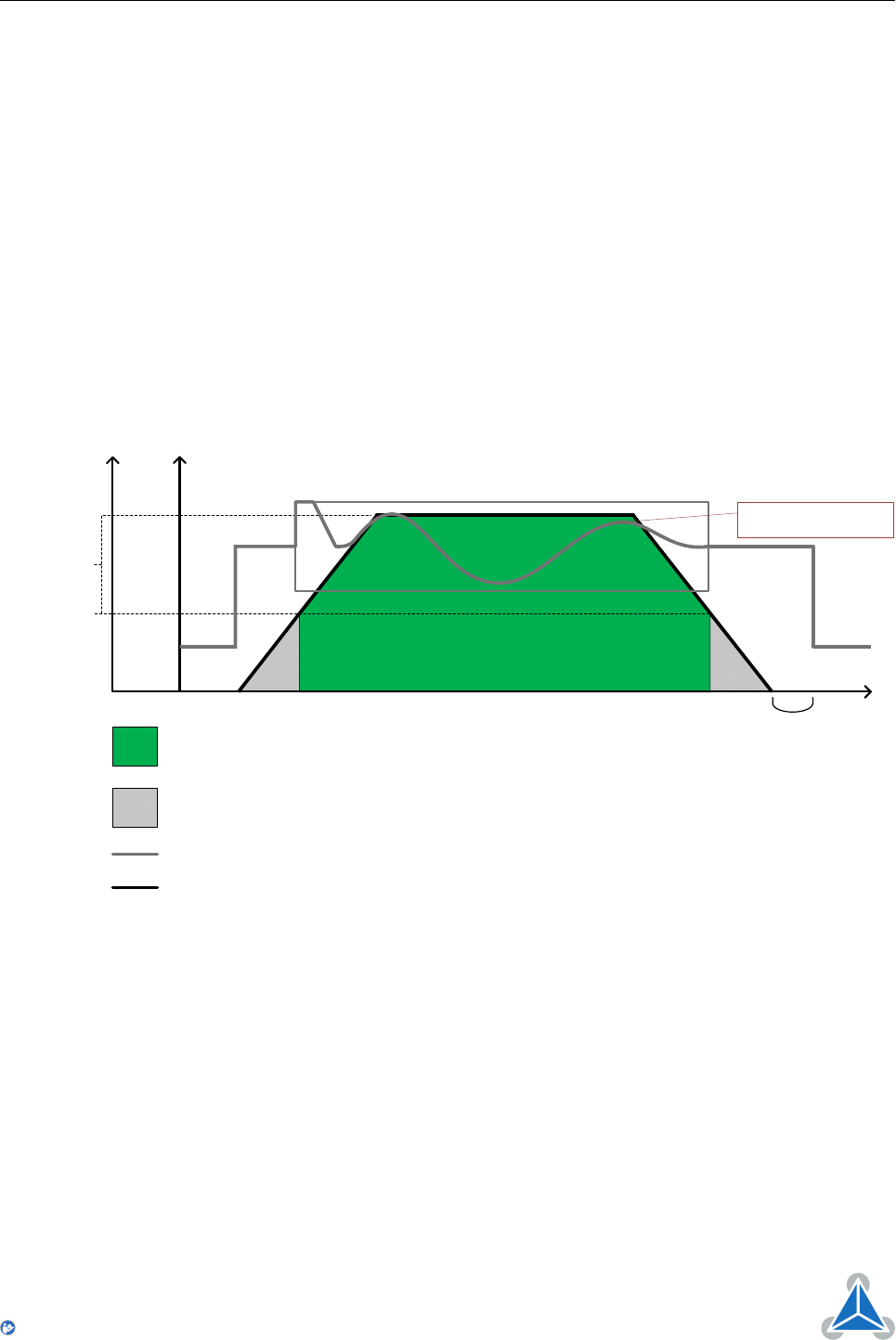
6.4 coolStep
This section gives an overview of the coolStep related parameters. Please bear in mind that the figure only
shows one example for a drive. There are parameters which concern the configuration of the current.
Other parameters are there for velocity regulation and for time adjustment.
Figure 11 shows all the adjustment points for coolStep. It is necessary to identify and configure the
thresholds for current (I6, I7 and I183) and velocity (V182). Furthermore the stallGuard2 feature has to be
adjusted (SG170). It can also be enabled if needed (SG181).
The reduction or increasing of the current in the coolStep area (depending on the load) has to be configured
using parameters I169 and I171.
In this chapter only basic axis parameters are mentioned which concern coolStep and stallGuard2. The
complete list of axis parameters in chapter 4 contains further parameters which offer more configuration
options.
Velocity
Time
T214
coolStep™ area
I 7
I 7
area without coolStep™
SG170
SG181
V182
I 6
I
183 I 183
Current
V123 Velocity and parameter
I 123 Current and parameter
T123 Time parameter
I 7
I 6
I 183
I 6/2*
* The lower threshold of the coolStep™ current can be adjusted up to I6/4. Refer to parameter 168.
The current depends on
the load of the motor.
SG123 stallGuard2™ parameter
Figure 11: coolStep Adjustment Points and Thresholds
©2017 TRINAMIC Motion Control GmbH & Co. KG, Hamburg, Germany
Terms of delivery and rights to technical change reserved.
Download newest version at www.trinamic.com
Read entire documentation.