User Manual
Table Of Contents
- 1 Features
- 2 First Steps with TMCL
- 3 TMCL and the TMCL-IDE — An Introduction
- 3.1 Binary Command Format
- 3.2 Reply Format
- 3.3 Standalone Applications
- 3.4 TMCL Command Overview
- 3.5 TMCL Commands by Subject
- 3.6 Detailed TMCL Command Descriptions
- 3.6.1 ROR (Rotate Right)
- 3.6.2 ROL (Rotate Left)
- 3.6.3 MST (Motor Stop)
- 3.6.4 MVP (Move to Position)
- 3.6.5 SAP (Set Axis Parameter)
- 3.6.6 GAP (Get Axis Parameter)
- 3.6.7 SGP (Set Global Parameter)
- 3.6.8 GGP (Get Global Parameter)
- 3.6.9 STGP (Store Global Parameter)
- 3.6.10 RSGP (Restore Global Parameter)
- 3.6.11 RFS (Reference Search)
- 3.6.12 SIO (Set Output)
- 3.6.13 GIO (Get Input)
- 3.6.14 CALC (Calculate)
- 3.6.15 COMP (Compare)
- 3.6.16 JC (Jump conditional)
- 3.6.17 JA (Jump always)
- 3.6.18 CSUB (Call Subroutine)
- 3.6.19 RSUB (Return from Subroutine)
- 3.6.20 WAIT (Wait for an Event to occur)
- 3.6.21 STOP (Stop TMCL Program Execution – End of TMCL Program)
- 3.6.22 SCO (Set Coordinate)
- 3.6.23 GCO (Get Coordinate)
- 3.6.24 CCO (Capture Coordinate)
- 3.6.25 ACO (Accu to Coordinate)
- 3.6.26 CALCX (Calculate using the X Register)
- 3.6.27 AAP (Accu to Axis Parameter)
- 3.6.28 AGP (Accu to Global Parameter)
- 3.6.29 CLE (Clear Error Flags)
- 3.6.30 EI (Enable Interrupt)
- 3.6.31 DI (Disable Interrupt)
- 3.6.32 VECT (Define Interrupt Vector)
- 3.6.33 RETI (Return from Interrupt)
- 3.6.34 Customer specific Command Extensions (UF0…UF7 – User Functions)
- 3.6.35 Request Target Position reached Event
- 3.6.36 TMCL Control Commands
- 4 Axis Parameters
- 5 Global Parameters
- 6 Hints and Tips
- 7 TMCL Programming Techniques and Structure
- 8 Figures Index
- 9 Tables Index
- 10 Supplemental Directives
- 11 Revision History

TMCM-3212 TMCL
™
Firmware Manual • Firmware Version V1.07 | Document Revision V1.04 • 2017-JUN-08
86 / 103
6 Hints and Tips
This chapter gives some hints and tips on using the functionality of TMCL, for example how to use and
parameterize the built-in reference search algorithm or using an incremental encoder. You will also find
basic information about stallGuard2™ and coolStep™ in this chapter.
6.1 Reference Search
The built-in reference search features switching point calibration and support for a home switch and/or
one or two end switches. The internal operation is based on a state machine that can be started, stopped
and monitored (instruction RFS, opcode 13). The settings of the automatic stop functions corresponding to
the end switches (axis parameters 12 and 13) do not influence the reference search.
Notes:
•
Until the reference switch is found for the first time, the searching speed set by axis parameter 194 is
used.
•
After hitting the reference switch, the motor slowly moves until the switch is released. Finally the
switch is re-entered in the other direction, setting the reference point to the center of the two
switching points. The speed used for this calibration is defined by axis parameter 195.
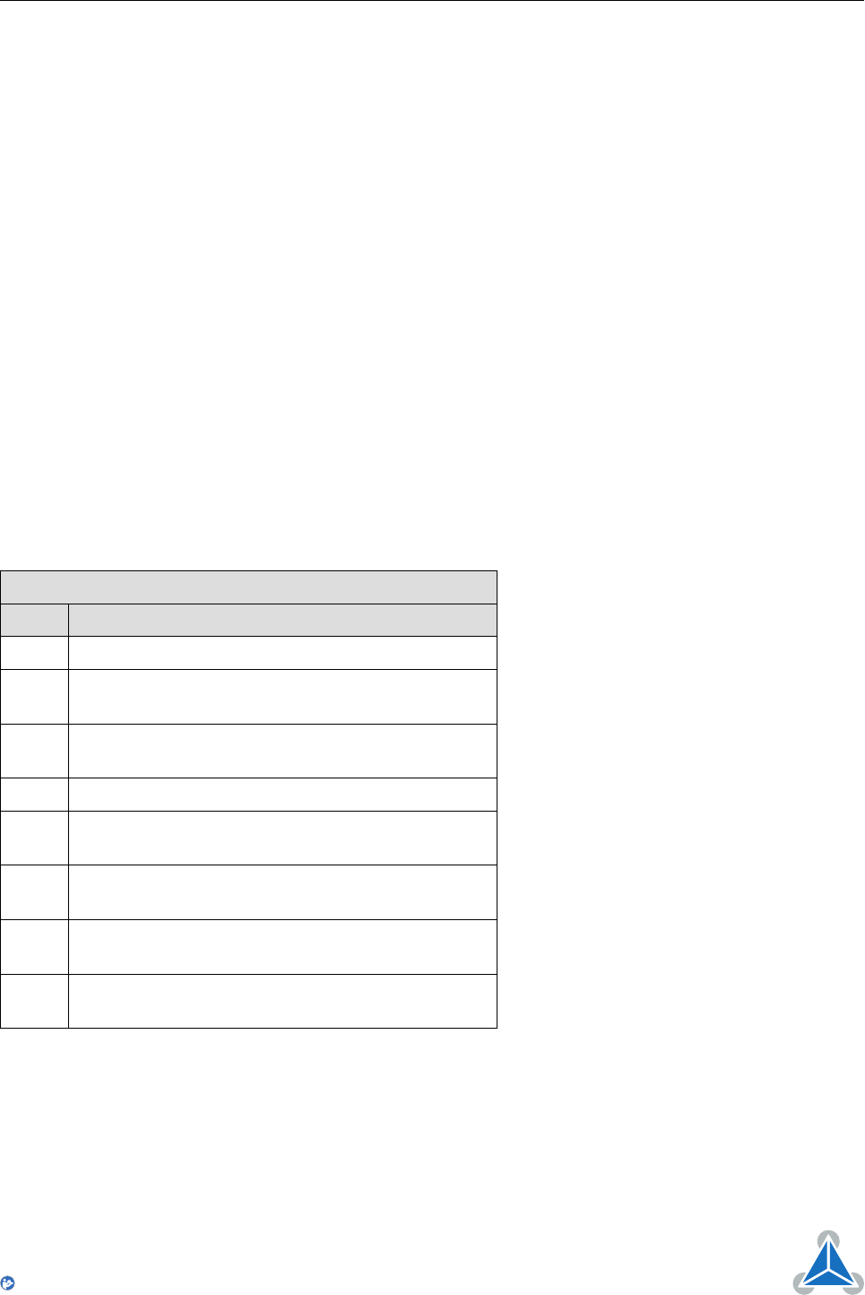
Axis parameter 193 defines the reference search mode to be used. Choose one of the reference search
modes shown in table 19 and in the following subsections:
Reference Search Modes
Value Description
1 search left stop switch only
2
search right stop switch, then search left stop
switch
3
search right stop switch, then search left stop
switch from both sides
4 search left stop switch from both sides
5
search home switch in negative direction, reverse
the direction when left stop switch reached
6
search home switch in positive direction, reverse
the direction when right stop switch reached
7
search home switch in positive direction, ignore
end switches
8
search home switch in negative direction, ignore
end switches
Table 19: Reference Search Modes
The drawings in the following subsections show how each reference search mode works. A linear stage
with two end points and a moving slider is used as example.
©2017 TRINAMIC Motion Control GmbH & Co. KG, Hamburg, Germany
Terms of delivery and rights to technical change reserved.
Download newest version at www.trinamic.com
Read entire documentation.


