
User Manual


Table Of Contents
- 1 Features
- 2 First Steps with TMCL
- 3 TMCL and the TMCL-IDE — An Introduction
- 3.1 Binary Command Format
- 3.2 Reply Format
- 3.3 Standalone Applications
- 3.4 TMCL Command Overview
- 3.5 TMCL Commands by Subject
- 3.6 Detailed TMCL Command Descriptions
- 3.6.1 ROR (Rotate Right)
- 3.6.2 ROL (Rotate Left)
- 3.6.3 MST (Motor Stop)
- 3.6.4 MVP (Move to Position)
- 3.6.5 SAP (Set Axis Parameter)
- 3.6.6 GAP (Get Axis Parameter)
- 3.6.7 SGP (Set Global Parameter)
- 3.6.8 GGP (Get Global Parameter)
- 3.6.9 STGP (Store Global Parameter)
- 3.6.10 RSGP (Restore Global Parameter)
- 3.6.11 RFS (Reference Search)
- 3.6.12 SIO (Set Output)
- 3.6.13 GIO (Get Input)
- 3.6.14 CALC (Calculate)
- 3.6.15 COMP (Compare)
- 3.6.16 JC (Jump conditional)
- 3.6.17 JA (Jump always)
- 3.6.18 CSUB (Call Subroutine)
- 3.6.19 RSUB (Return from Subroutine)
- 3.6.20 WAIT (Wait for an Event to occur)
- 3.6.21 STOP (Stop TMCL Program Execution – End of TMCL Program)
- 3.6.22 SCO (Set Coordinate)
- 3.6.23 GCO (Get Coordinate)
- 3.6.24 CCO (Capture Coordinate)
- 3.6.25 ACO (Accu to Coordinate)
- 3.6.26 CALCX (Calculate using the X Register)
- 3.6.27 AAP (Accu to Axis Parameter)
- 3.6.28 AGP (Accu to Global Parameter)
- 3.6.29 CLE (Clear Error Flags)
- 3.6.30 EI (Enable Interrupt)
- 3.6.31 DI (Disable Interrupt)
- 3.6.32 VECT (Define Interrupt Vector)
- 3.6.33 RETI (Return from Interrupt)
- 3.6.34 Customer specific Command Extensions (UF0…UF7 – User Functions)
- 3.6.35 Request Target Position reached Event
- 3.6.36 TMCL Control Commands
- 4 Axis Parameters
- 5 Global Parameters
- 6 Hints and Tips
- 7 TMCL Programming Techniques and Structure
- 8 Figures Index
- 9 Tables Index
- 10 Supplemental Directives
- 11 Revision History
TMCM-3212 TMCL
™
Firmware Manual • Firmware Version V1.07 | Document Revision V1.04 • 2017-JUN-08
72 / 103
4 Axis Parameters
Most motor controller features of the TMCM-3212 module are controlled by axis parameters. Axis
parameters can be modified or read using SAP, GAP, AAP, STAP and RSAP commands. This chapter
describes all axis parameters that can be used on the TMCM-3212 module.
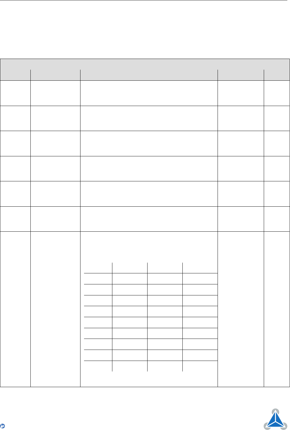
All Axis Parameters of the TMCM-3212 Module
Number Axis Parameter Description Range [Units] Access
0 Target position The desired target position in position mode -2147483648
. . . 2147483647
[µsteps]
RW
1 Actual position
The actual position of the motor. Stop the motor
before overwriting it. Should normally only be
overwritten for reference position setting.
-2147483648
. . . 2147483647
[µsteps]
RW
2 Target speed
The desired speed in velocity mode. Not valid in
position mode.
-7999774
. . . 7999774
[pps]
RW
3 Actual speed The actual speed of the motor. -7999774
. . . 7999774
[pps]
R
4 Maximum
positioning
speed
The maximum speed used for positioning
ramps.
0. . . 7999774
[pps]
RW
5 Maximum
acceleration
Maximum acceleration in positioning ramps. Ac-
celeration and deceleration value in velocity
mode.
0. . . 7629278
[pps
2
]
RW
6 Maximum
current
Motor current used when motor is running. The
maximum value is 255 which means 100% of
the maximum current of the module.
The current can be adjusted in 32 steps:
0. . . 7 79. . . 87 160. . . 167 240. . . 247
8. . . 15 88. . . 95 168. . . 175 248. . . 255
16. . . 23 96. . . 103 176. . . 183
24. . . 31 104. . . 111 184. . . 191
32. . . 39 112. . . 119 192. . . 199
40. . . 47 120. . . 127 200. . . 207
48. . . 55 128. . . 135 208. . . 215
56. . . 63 136. . . 143 216. . . 223
64. . . 71 144. . . 151 224. . . 231
72. . . 79 152. . . 159 232. . . 239
The most important setting, as too high values can
cause motor damage.
0. . . 255 RW
©2017 TRINAMIC Motion Control GmbH & Co. KG, Hamburg, Germany
Terms of delivery and rights to technical change reserved.
Download newest version at www.trinamic.com
Read entire documentation.