
User Manual


Table Of Contents
- 1 Features
- 2 First Steps with TMCL
- 3 TMCL and the TMCL-IDE — An Introduction
- 3.1 Binary Command Format
- 3.2 Reply Format
- 3.3 Standalone Applications
- 3.4 TMCL Command Overview
- 3.5 TMCL Commands by Subject
- 3.6 Detailed TMCL Command Descriptions
- 3.6.1 ROR (Rotate Right)
- 3.6.2 ROL (Rotate Left)
- 3.6.3 MST (Motor Stop)
- 3.6.4 MVP (Move to Position)
- 3.6.5 SAP (Set Axis Parameter)
- 3.6.6 GAP (Get Axis Parameter)
- 3.6.7 SGP (Set Global Parameter)
- 3.6.8 GGP (Get Global Parameter)
- 3.6.9 STGP (Store Global Parameter)
- 3.6.10 RSGP (Restore Global Parameter)
- 3.6.11 RFS (Reference Search)
- 3.6.12 SIO (Set Output)
- 3.6.13 GIO (Get Input)
- 3.6.14 CALC (Calculate)
- 3.6.15 COMP (Compare)
- 3.6.16 JC (Jump conditional)
- 3.6.17 JA (Jump always)
- 3.6.18 CSUB (Call Subroutine)
- 3.6.19 RSUB (Return from Subroutine)
- 3.6.20 WAIT (Wait for an Event to occur)
- 3.6.21 STOP (Stop TMCL Program Execution – End of TMCL Program)
- 3.6.22 SCO (Set Coordinate)
- 3.6.23 GCO (Get Coordinate)
- 3.6.24 CCO (Capture Coordinate)
- 3.6.25 ACO (Accu to Coordinate)
- 3.6.26 CALCX (Calculate using the X Register)
- 3.6.27 AAP (Accu to Axis Parameter)
- 3.6.28 AGP (Accu to Global Parameter)
- 3.6.29 CLE (Clear Error Flags)
- 3.6.30 EI (Enable Interrupt)
- 3.6.31 DI (Disable Interrupt)
- 3.6.32 VECT (Define Interrupt Vector)
- 3.6.33 RETI (Return from Interrupt)
- 3.6.34 Customer specific Command Extensions (UF0…UF7 – User Functions)
- 3.6.35 Request Target Position reached Event
- 3.6.36 TMCL Control Commands
- 4 Axis Parameters
- 5 Global Parameters
- 6 Hints and Tips
- 7 TMCL Programming Techniques and Structure
- 8 Figures Index
- 9 Tables Index
- 10 Supplemental Directives
- 11 Revision History
TMCM-3212 TMCL
™
Firmware Manual • Firmware Version V1.07 | Document Revision V1.04 • 2017-JUN-08
68 / 103
3.6.35 Request Target Position reached Event
This command is the only exception to the TMCL protocol, as it sends two replies: One immediately after
the command has been executed (like all other commands also), and one additional reply that will be
sent when the motor has reached its target position. This instruction can only be used in direct mode (in
standalone mode, it is covered by the WAIT command) and hence does not have a mnemonic.
Internal function: send an additional reply when a motor has reached its target position.
Related commands: none.
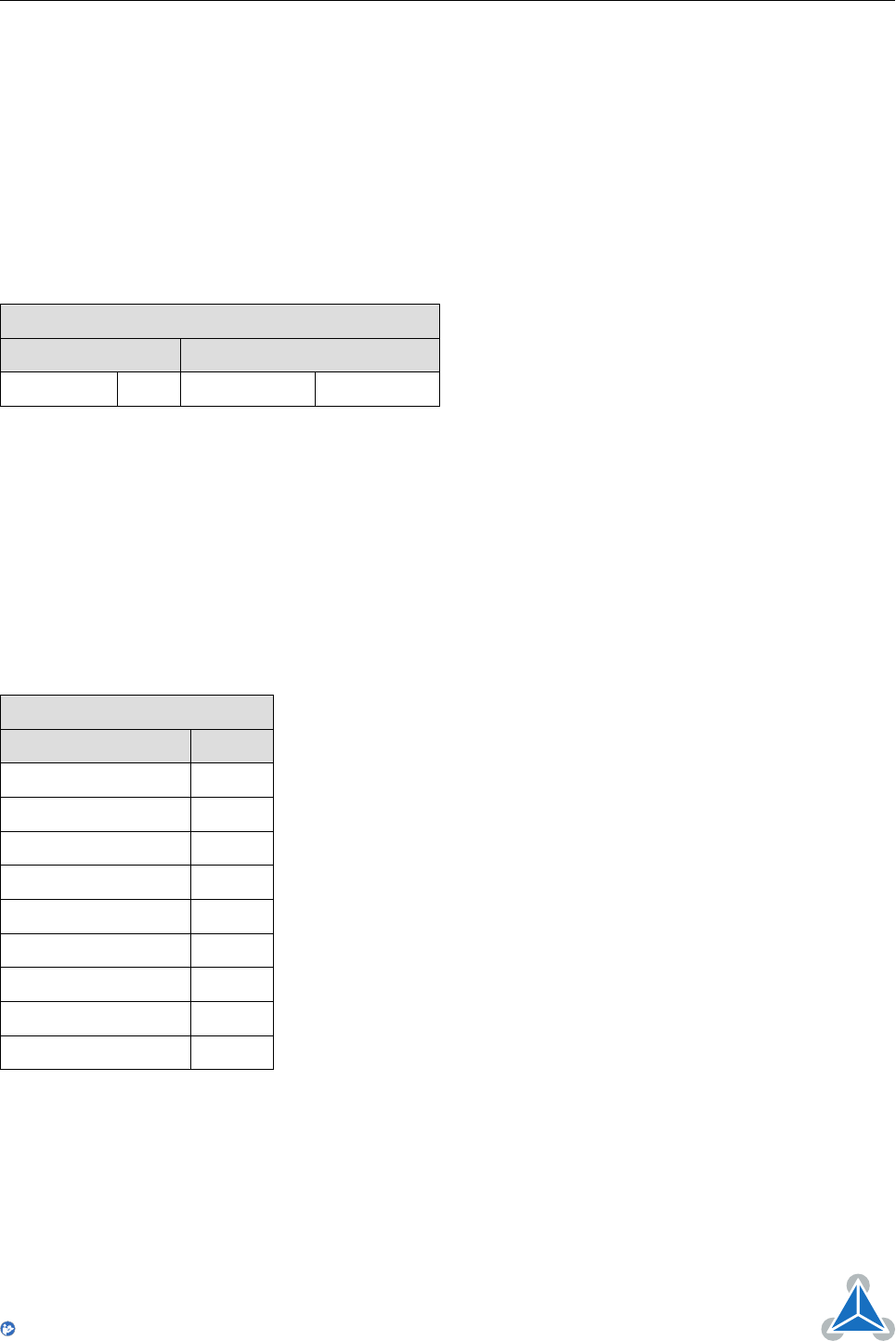
Binary Representation
Instruction Type Motor/Bank Value
138 0/1 0 (don’t care) <bit vector>
With command 138 the value field is a bit vector. It shows for which motors one would like to have a
position reached message. The value field contains a bit mask where every bit stands for one motor. Bit 0
stands for motor #0, bit 1 stands for motor #1, bit 2 stands for motor #2 and so on. With the type field
set to 0, only for the next MVP command that follows this command a position reached message will be
generated. With type set to 1 a position reached message will be generated for every MVP command that
follows this command. It is recommended to use the latter option.
Example
Get target position reached message for motors #2 and #3.
Binary Form for this example
Field Value
Target address 01
h
Instruction number 8A
h
Type 01
h
Motor/Bank 00
h
Value (Byte 3) 00
h
Value (Byte 2) 00
h
Value (Byte 1) 00
h
Value (Byte 0) 05
h
Checksum 91
h
©2017 TRINAMIC Motion Control GmbH & Co. KG, Hamburg, Germany
Terms of delivery and rights to technical change reserved.
Download newest version at www.trinamic.com
Read entire documentation.