
User Manual


Table Of Contents
- 1 Features
- 2 First Steps with TMCL
- 3 TMCL and the TMCL-IDE — An Introduction
- 3.1 Binary Command Format
- 3.2 Reply Format
- 3.3 Standalone Applications
- 3.4 TMCL Command Overview
- 3.5 TMCL Commands by Subject
- 3.6 Detailed TMCL Command Descriptions
- 3.6.1 ROR (Rotate Right)
- 3.6.2 ROL (Rotate Left)
- 3.6.3 MST (Motor Stop)
- 3.6.4 MVP (Move to Position)
- 3.6.5 SAP (Set Axis Parameter)
- 3.6.6 GAP (Get Axis Parameter)
- 3.6.7 SGP (Set Global Parameter)
- 3.6.8 GGP (Get Global Parameter)
- 3.6.9 STGP (Store Global Parameter)
- 3.6.10 RSGP (Restore Global Parameter)
- 3.6.11 RFS (Reference Search)
- 3.6.12 SIO (Set Output)
- 3.6.13 GIO (Get Input)
- 3.6.14 CALC (Calculate)
- 3.6.15 COMP (Compare)
- 3.6.16 JC (Jump conditional)
- 3.6.17 JA (Jump always)
- 3.6.18 CSUB (Call Subroutine)
- 3.6.19 RSUB (Return from Subroutine)
- 3.6.20 WAIT (Wait for an Event to occur)
- 3.6.21 STOP (Stop TMCL Program Execution – End of TMCL Program)
- 3.6.22 SCO (Set Coordinate)
- 3.6.23 GCO (Get Coordinate)
- 3.6.24 CCO (Capture Coordinate)
- 3.6.25 ACO (Accu to Coordinate)
- 3.6.26 CALCX (Calculate using the X Register)
- 3.6.27 AAP (Accu to Axis Parameter)
- 3.6.28 AGP (Accu to Global Parameter)
- 3.6.29 CLE (Clear Error Flags)
- 3.6.30 EI (Enable Interrupt)
- 3.6.31 DI (Disable Interrupt)
- 3.6.32 VECT (Define Interrupt Vector)
- 3.6.33 RETI (Return from Interrupt)
- 3.6.34 Customer specific Command Extensions (UF0…UF7 – User Functions)
- 3.6.35 Request Target Position reached Event
- 3.6.36 TMCL Control Commands
- 4 Axis Parameters
- 5 Global Parameters
- 6 Hints and Tips
- 7 TMCL Programming Techniques and Structure
- 8 Figures Index
- 9 Tables Index
- 10 Supplemental Directives
- 11 Revision History
TMCM-3212 TMCL
™
Firmware Manual • Firmware Version V1.07 | Document Revision V1.04 • 2017-JUN-08
12 / 103
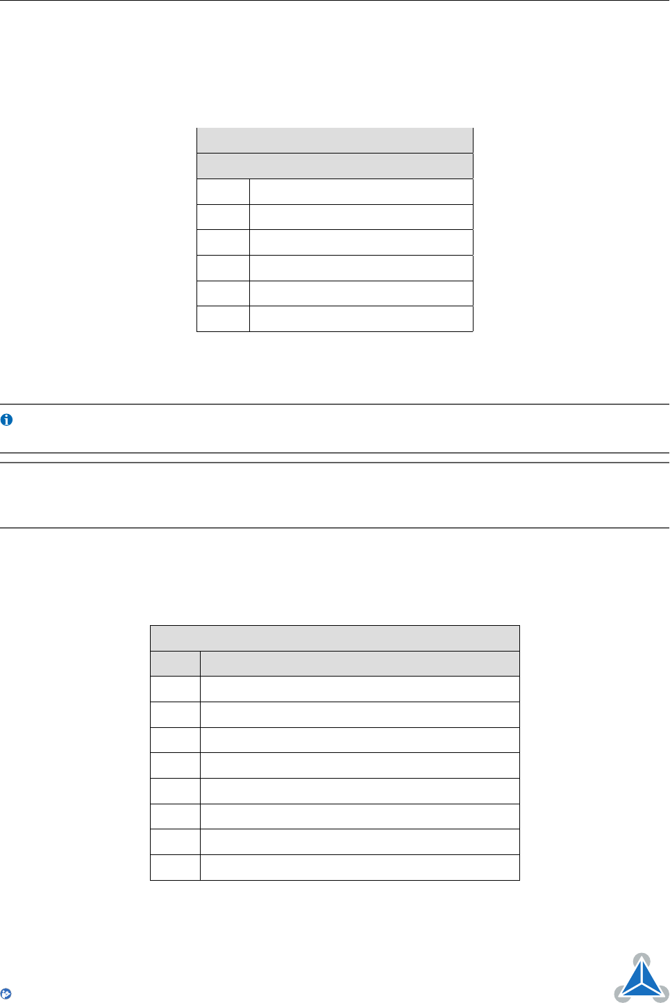
3.2 Reply Format
Every time a command has been sent to a module, the module sends a reply.
The reply format with RS-232, RS-485, RS-422 and USB is as follows:
TMCL Reply Format
Bytes Meaning
1 Reply address
1 Module address
1 Status (e.g. 100 means no error)
1 Command number
4 Value (MSB first!)
1 Checksum
Table 3: TMCL Reply Format
Info
The checksum is also calculated by adding up all the other bytes using an 8-bit
addition. Do not send the next command before having received the reply!
Note
When using CAN interface, the reply does not contain an address byte and a
checksum byte. With CAN, the CAN-ID is used as the reply address and the
checksum is not needed because the CAN bus uses hardware CRC checking.
3.2.1 Status Codes
The reply contains a status code. The status code can have one of the following values:
TMCL Status Codes
Code Meaning
100 Successfully executed, no error
101 Command loaded into TMCL program EEPROM
1 Wrong checksum
2 Invalid command
3 Wrong type
4 Invalid value
5 Configuration EEPROM locked
6 Command not available
Table 4: TMCL Status Codes
©2017 TRINAMIC Motion Control GmbH & Co. KG, Hamburg, Germany
Terms of delivery and rights to technical change reserved.
Download newest version at www.trinamic.com
Read entire documentation.