
User Manual


Table Of Contents
- 1 Features
- 2 First Steps with TMCL
- 3 TMCL and the TMCL-IDE — An Introduction
- 3.1 Binary Command Format
- 3.2 Reply Format
- 3.3 Standalone Applications
- 3.4 TMCL Command Overview
- 3.5 TMCL Commands by Subject
- 3.6 Detailed TMCL Command Descriptions
- 3.6.1 ROR (Rotate Right)
- 3.6.2 ROL (Rotate Left)
- 3.6.3 MST (Motor Stop)
- 3.6.4 MVP (Move to Position)
- 3.6.5 SAP (Set Axis Parameter)
- 3.6.6 GAP (Get Axis Parameter)
- 3.6.7 SGP (Set Global Parameter)
- 3.6.8 GGP (Get Global Parameter)
- 3.6.9 STGP (Store Global Parameter)
- 3.6.10 RSGP (Restore Global Parameter)
- 3.6.11 RFS (Reference Search)
- 3.6.12 SIO (Set Output)
- 3.6.13 GIO (Get Input)
- 3.6.14 CALC (Calculate)
- 3.6.15 COMP (Compare)
- 3.6.16 JC (Jump conditional)
- 3.6.17 JA (Jump always)
- 3.6.18 CSUB (Call Subroutine)
- 3.6.19 RSUB (Return from Subroutine)
- 3.6.20 WAIT (Wait for an Event to occur)
- 3.6.21 STOP (Stop TMCL Program Execution – End of TMCL Program)
- 3.6.22 SCO (Set Coordinate)
- 3.6.23 GCO (Get Coordinate)
- 3.6.24 CCO (Capture Coordinate)
- 3.6.25 ACO (Accu to Coordinate)
- 3.6.26 CALCX (Calculate using the X Register)
- 3.6.27 AAP (Accu to Axis Parameter)
- 3.6.28 AGP (Accu to Global Parameter)
- 3.6.29 CLE (Clear Error Flags)
- 3.6.30 EI (Enable Interrupt)
- 3.6.31 DI (Disable Interrupt)
- 3.6.32 VECT (Define Interrupt Vector)
- 3.6.33 RETI (Return from Interrupt)
- 3.6.34 Customer specific Command Extensions (UF0…UF7 – User Functions)
- 3.6.35 Request Target Position reached Event
- 3.6.36 TMCL Control Commands
- 4 Axis Parameters
- 5 Global Parameters
- 6 Hints and Tips
- 7 TMCL Programming Techniques and Structure
- 8 Figures Index
- 9 Tables Index
- 10 Supplemental Directives
- 11 Revision History
TMCM-3212 TMCL
™
Firmware Manual • Firmware Version V1.07 | Document Revision V1.04 • 2017-JUN-08
11 / 103
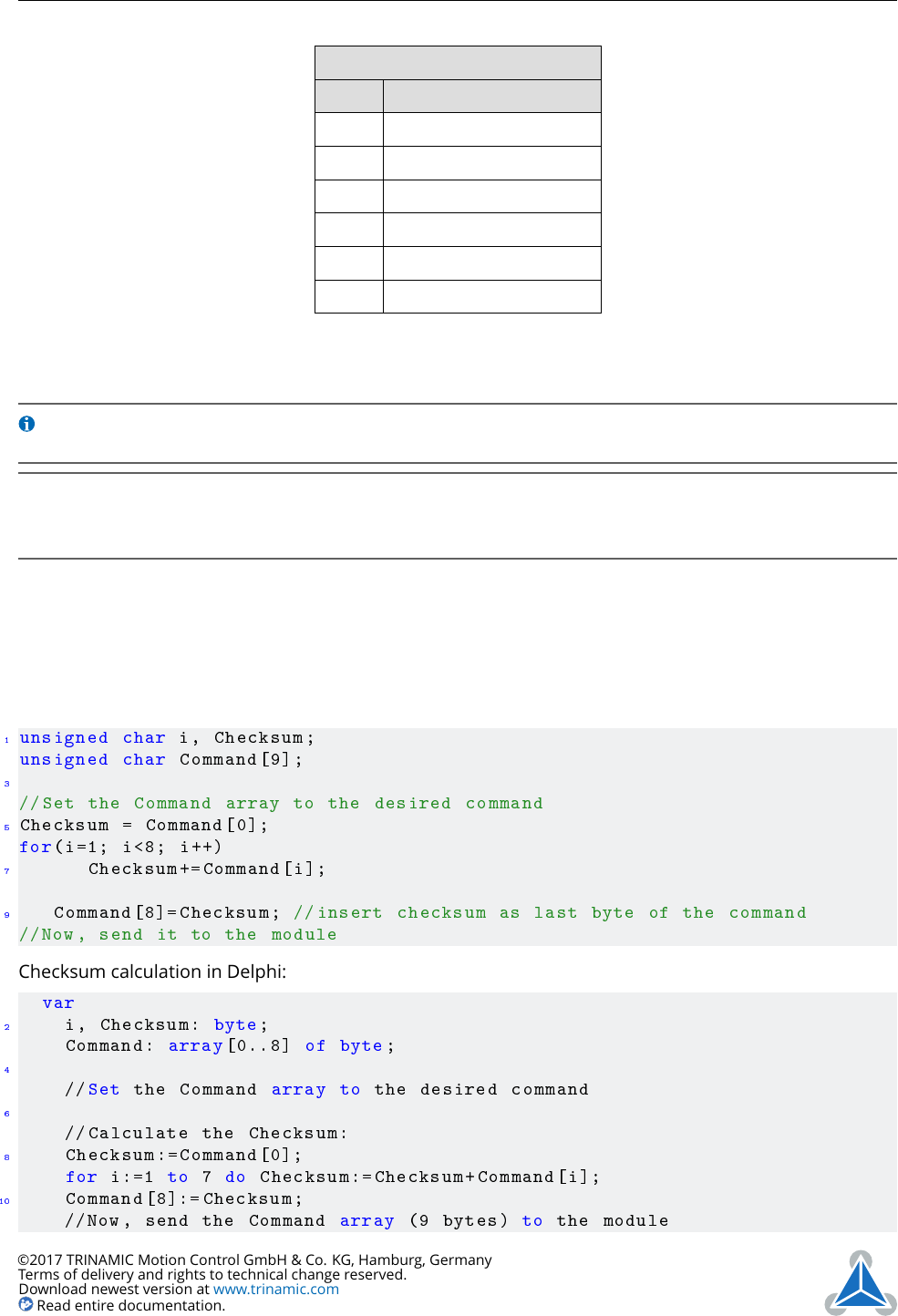
TMCL Command Format
Bytes Meaning
1 Module address
1 Command number
1 Type number
1 Motor or Bank number
4 Value (MSB first!)
1 Checksum
Table 2: TMCL Command Format
Info
The checksum is calculated by accumulating all the other bytes using an 8-bit
addition.
Note
When using the CAN interface, leave out the address byte and the checksum byte.
With CAN, the CAN-ID is used as the module address and the checksum is not
needed because CAN bus uses hardware CRC checking.
3.1.1 Checksum Calculation
As mentioned above, the checksum is calculated by adding up all bytes (including the module address
byte) using 8-bit addition. Here are two examples which show how to do this:
Checksum calculation in C:
1
unsigned char i, Checksum ;
unsigned char Command [9];
3
//Set the Command array to the desired command
5
Checksum = Command [0];
for(i=1; i <8; i++)
7
Checksum +=Command[i];
9
Command [8]= Checksum ; // insert checksum as last byte of the command
//Now , send it to the module
Checksum calculation in Delphi:
var
2
i, Checksum: byte;
Command: array [0..8] of byte;
4
//Set the Command array to the desired command
6
// Calculate the Checksum:
8
Checksum :=Command [0];
for i:=1 to 7 do Checksum := Checksum+Command[i];
10
Command [8]:= Checksum;
//Now , send the Command array (9 bytes) to the module
©2017 TRINAMIC Motion Control GmbH & Co. KG, Hamburg, Germany
Terms of delivery and rights to technical change reserved.
Download newest version at www.trinamic.com
Read entire documentation.