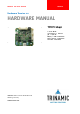
MODULES FOR BLDC MOTORS MODULES Hardware Version 1.0 HARDWARE MANUAL + + TMCM-1640 1-axis BLDC controller / driver 5A / 24V DC RS485 + USB interface hall sensor interface encoder interface + TRINAMIC Motion Control GmbH & Co. KG Hamburg, Germany www.trinamic.
TMCM-1640 Hardware Manual (V1.05 / 2017-MAR-12) Table of Contents 1 2 3 4 5 6 7 8 Life support policy ....................................................................................................................................................... 3 Features ........................................................................................................................................................................... 4 Order codes ........................................................
TMCM-1640 Hardware Manual (V1.05 / 2017-MAR-12) 1 Life support policy TRINAMIC Motion Control GmbH & Co. KG does not authorize or warrant any of its products for use in life support systems, without the specific written consent of TRINAMIC Motion Control GmbH & Co. KG. Life support systems are equipment intended to support or sustain life, and whose failure to perform, when properly used in accordance with instructions provided, can be reasonably expected to result in personal injury or death.
TMCM-1640 Hardware Manual (V1.05 / 2017-MAR-12) 4 2 Features The TMCM-1640 is a highly compact controller/driver module for brushless DC (BLDC) motors with up to 5A coil current, optional encoder and/or hall sensor feedback. For communication the module offers RS485 and (mini-)USB interfaces. Applications Compact single-axis brushless DC motor solutions Electrical data Supply voltage: +24VDC nom. (+12V… +28.
TMCM-1640 Hardware Manual (V1.05 / 2017-MAR-12) 5 3 Order codes Cables are not included. Add the TMCM-1640-CABLE to your order if required. Order code TMCM-1640 Component parts TMCM-1640-CABLE Related motors QBL4208-41-04-006 QBL4208-61-04-013 Dimensions [mm] Description 1-axis BLDC controller/driver module with up to 5A / 42 x 42 x 15 28.5V. RS485 and USB 2.0 interface Cable-loom for TMCM-1640 QMot BLDC motor 42 mm, 4000RPM, 0.06Nm QMot BLDC motor 42 mm, 4000RPM, 0.13Nm Table 3.
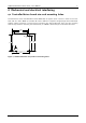
TMCM-1640 Hardware Manual (V1.05 / 2017-MAR-12) 6 4 Mechanical and electrical interfacing 4.1 Controller/driver board size and mounting holes The dimensions of the controller/driver board (TMCM-164) are approx. 42mm x 42mm in order to fit on the back side of a 42mm NEMA 17 brushless DC motor. Maximum component height (height above PCB level) without mating connectors is around 10mm and about 3mm below PCB level.
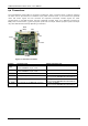
TMCM-1640 Hardware Manual (V1.05 / 2017-MAR-12) 7 4.2 Connectors The controller/driver board offers 6 connectors including the motor connector which is used for attaching the motor coils to the electronics. In addition to the power connector there is one connector for (optional) motor hall sensor signals and one connector for (optional) incremental encoder signals. For serial communication a mini-USB connector has been integrated on-board.
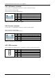
TMCM-1640 Hardware Manual (V1.05 / 2017-MAR-12) 8 4.2.1 Power connector A 2-pin Tyco electronics (formerly AMP) MTA-100 series connector (3-640456-2) is used as power connector on-board. Mating connector: Tyco electronics (formerly AMP) MTA-100 series (3-640440-2) 2 1 Pin Label 1 +U 2 GND Description Module + driver stage power supply input Module ground (power supply and signal ground) Table 4.
TMCM-1640 Hardware Manual (V1.05 / 2017-MAR-12) 9 4.2.3 Hall sensor connector A 2mm pitch 5 pin JST B5B-PH-K connector is used for hall sensor signals. Mating connector housing: PHR-5 Mating connector contacts: SPH-002T-P0.5S. 5 1 Pin 1 2 3 4 5 Label GND +5V HALL_1 HALL_2 HALL_3 Description Hall sensor supply and signal ground +5V output for hall sensor supply Hall sensor signal 1 Hall sensor signal 2 Hall sensor signal 3 Table 4.3: Connector for hall sensor signals 4.2.
TMCM-1640 Hardware Manual (V1.05 / 2017-MAR-12) 10 4.2.6 GPIOs and RS485 connector A 2mm pitch 8 pin JST B8B-PH-K connector is used for connecting general purpose inputs and outputs. Mating connector housing: PHR-8 Mating connector contacts: SPH-002T-P0.5S 1 8 Pin 1 2 Label GND +5V 3 AIN 4 IN_0 5 IN_1 6 7 OUT RS485+ Description Signal and system ground +5V output for supply of external circuit (max.
TMCM-1640 Hardware Manual (V1.05 / 2017-MAR-12) 11 4.3 Input/output circuits 4.3.1 Hall sensor input The hall sensor input circuit supports +5V push-pull (TTL) and open-collector hall sensor signals. In order to support open-collector signals the input circuit offers 2k7 pull-up resistors to +5V (generated on-board from power supply voltage). Figure 4.3: Hall sensor input circuit 4.3.2 Encoder input The encoder input circuit supports +5V push-pull (TTL) and open-collector hall sensor signals.
TMCM-1640 Hardware Manual (V1.05 / 2017-MAR-12) 4.3.3 General purpose inputs/outputs Figure 4.5: General purpose input/output circuit Copyright © 2011-2017, TRINAMIC Motion Control GmbH & Co.
TMCM-1640 Hardware Manual (V1.05 / 2017-MAR-12) 13 5 Operational ratings The operational ratings shown below should be used as design values. In no case should the maximum values been exceeded during operation. Symbol Parameter Min Typ Max Unit +U Power supply voltage for operation 9 24 28.5 V DC ICOIL Continuous motor current (RMS) 0 3 5 A ISUPPLY Power supply current << ICOIL 1.
TMCM-1640 Hardware Manual (V1.05 / 2017-MAR-12) 14 6 Functional description In Figure 6.1 the main parts of the TMCM-1640 module are shown. The module mainly consists of the Cortex™-M3 CPU, TRINAMICs TMC603A 3-phase pre-driver, the MOSFET driver-stage, and the USB 2.0 interface. EEPROM Hall sensor feedback optional RS485 USB 2.0 Cortex_M3 CPU AIN MOSFET driver stage TMC603 3-phase pre-driver BLDC Motor DIN_1/2 LED_Temp LED_Curlimit 9… +28.5V DC 2 5V 3.
TMCM-1640 Hardware Manual (V1.05 / 2017-MAR-12) 7 Revision history 7.1 Document revision Version Date 0.90 1.00 1.01 1.02 1.03 1.04 1.