
User Manual


TMCM-1276 CANopen
®
Firmware Manual • Firmware Version V3.22 | Document Revision V1.00 • 2018-JUN-28
98 / 114
9 Cyclic synchonous Position Mode
The cyclic synchronous position mode is used to directly control the position of the motor. It contains
limit functions, but not a trajectory generator. The trajectory generator is located in the control device
(the master), not in the drive device. In cyclic synchronous manner, the control device provides a target
position to the drive device, which performs position control, velocity control and torque control.
The main control parameters are the target position (object 607A
h
, see section 9.1.7) and the interpolation
time period (object 60C2
h
, see section 9.1.10). The drive automatically sets the velocity in such a manner
that the next target position is reached within the interpolation time period. Acceleration and deceleration
ramps are not used in this mode.
The cyclic synchronous position mode covers the following sub-functions:
• Position demand value input directly via an object.
• Monitoring of the position.
• Limiting the position using the software limits or the hardware limit switches.
9.1 Detailed Object Specifications
9.1.1 Object 6040
h
: Control Word
This object indicates the received command controlling the power drive system finite state automaton (PDS
FSA). The CiA-402 state machine can be controlled using this object. Please refer to figure 8 for detailed
information. The cyclic synchronous position mode does not use any mode specific bits of the control word.
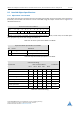
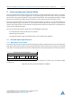
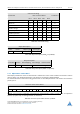
Structure of the Control Word
15 9 8 7 6 4 3 2 1 0
nu h fr nu eo qs ev so
MSB LSB
Legend: nu=not used; h=halt; fr=fault reset; eo=enable operation; qs=quick stop; ev=enable voltage;
so=switch on.
Table 296: Structure of the Control Word in csp Mode
©2018 TRINAMIC Motion Control GmbH & Co. KG, Hamburg, Germany
Terms of delivery and rights to technical change reserved.
Download newest version at www.trinamic.com