
User Manual


TMCM-1260 Hardware Manual • Hardware Version V1.10 | Document Revision V1.20 • 2018-05-17
8 / 30
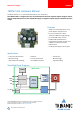
4 Connectors
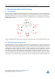
The TMCM-1260 offers six connectors altogehter. There is one power supply connector and two interface
connectors - one with five pins for RS485 and CAN and a dedicated micro-USB connector. All other inputs
and outputs are concentrated on one 8 pin connector. Furthermore, there is one connection for the
stepper motor with four pins with a choice between two connectors with different size, pitch and current
rating. While the smaller one supports motor currents up-to 3A RMS (half the max. current of the module)
the larger supports the full current (6A RMS).
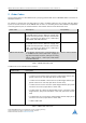
NOTICE
Start with power supply OFF and do not connect or disconnect motor dur-
ing operation!
Motor cable and motor inductivity might lead to voltage spikes
when the motor is (dis)connected while energized. These voltage spikes might
exceed voltage limits of the driver MOSFETs and might permanently damage
them. Therefore, always switch off / disconnect power supply or at least disable
driver stage before connecting / disconnecting motor.
I/O
RS485 + CAN
1 5
USB
1
8
Motor
14
Power
1
4
14
Figure 2: TMCM-1260 connectors
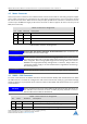
Connector Types and Mating Connectors
Connector Connector type on-board Mating connector type
Power JST B4P-VH
(JST VH series, 4pins, 3.96mm pitch)
Connector housing: JST VHR-4N
Contacts: JST SVH-21T-P1.1
Wire: 0.83mm2, AWG 18
Motor JST JST B4P-VH
(JST VH series, 4pins, 3.96mm pitch)
or
JST JST B4B-EH-A
(JST EH series, 4pins, 2.5mm pitch)
Connector housing: JST VHR-4N
Contacts: JST SVH-21T-P1.1
Wire: 0.83mm2, AWG 18
or
Connector housing: JST EHR-4
Contacts: JST SEH-001T-P0.6
Wire: 0.33mm2, AWG 22
RS485+CAN JST B5B-PH-K-S
(JST PH series, 5pins, 2mm pitch)
Connector housing: JST PHR-5
Contacts: JST SPH-002T-P0.5S
Wire: 0.22mm2, AWG 24
©2018 TRINAMIC Motion Control GmbH & Co. KG, Hamburg, Germany
Terms of delivery and rights to technical change reserved.
Download newest version at www.trinamic.com