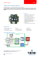
MODULE Module for Stepper TMCM-1260 Hardware Manual Hardware Version V1.10 | Document Revision V1.20 • 2018-05-17 The TMCM-1260 is a single axis motor controller/driver board for 2-phase bipolar stepper motors with up-to 6A RMS motor current and 48V DC supply. It supports 6-point ramps in addition to linear ramps.
/ 30 TMCM-1260 Hardware Manual • Hardware Version V1.10 | Document Revision V1.20 • 2018-05-17 Contents 1 Features 3 2 Order Codes 5 3 Mechanical and Electrical Interfacing 3.1 Size of board . . . . . . . . . . . . . . . . . . . . . . . . . . . . . . . . . . . . . . . . . . . . . . . . 3.2 Board mounting considerations . . . . . . . . . . . . . . . . . . . . . . . . . . . . . . . . . . . . 7 7 7 4 Connectors 4.1 Power Supply Input Connector 4.2 Motor Connector . . . . . . . . 4.
TMCM-1260 Hardware Manual • Hardware Version V1.10 | Document Revision V1.20 • 2018-05-17 1 3 / 30 Features The TMCM-1260 is a single axis motor controller/driver board for 2-phase bipolar stepper motors with up-to 6A RMS (8.4A peak) motor coil current. It supports linear ramps and unique sixPoint™ ramps. It offers on-board sensOstep encoder and in addition, support for connection of external (incremental A/B) encoder.
TMCM-1260 Hardware Manual • Hardware Version V1.10 | Document Revision V1.20 • 2018-05-17 4 / 30 • Encoder input for incremental A/B encoder signals (shared with general purpose digital inputs) • 1 analog input (0..10V nom. input range) • HOME switch input (shared with analog input) Mechanical data • Board size: 60mm x 60mm, height 26mm max.
/ 30 TMCM-1260 Hardware Manual • Hardware Version V1.10 | Document Revision V1.20 • 2018-05-17 2 Order Codes The standard version of the TMCM-1260 is pre-programmed with either TRINAMIC TMCL™ firmware or CANopen firmware. On request a version with 3 analog inputs (0..10V) is available instead of one analog and two digital inputs on the I/O connector of the TMCM-1260.
TMCM-1260 Hardware Manual • Hardware Version V1.10 | Document Revision V1.20 • 2018-05-17 6 / 30 The TMCM-1260 is also available as motor mounted version together with a selection of NEMA23 / NEMA24 flange size stepper motor. Please refer to PD57/60-x-1260 PANdrive hardware manual for further details. ©2018 TRINAMIC Motion Control GmbH & Co. KG, Hamburg, Germany Terms of delivery and rights to technical change reserved. Download newest version at www.trinamic.
TMCM-1260 Hardware Manual • Hardware Version V1.10 | Document Revision V1.20 • 2018-05-17 3 3.1 7 / 30 Mechanical and Electrical Interfacing Size of board The board with the controller/driver electronics has an overall size of 60mm x 60mm x 26mm without mating connectors. Maximum component height without mating connectors is around 21mm above and 3mm below PCB level.
TMCM-1260 Hardware Manual • Hardware Version V1.10 | Document Revision V1.20 • 2018-05-17 4 8 / 30 Connectors The TMCM-1260 offers six connectors altogehter. There is one power supply connector and two interface connectors - one with five pins for RS485 and CAN and a dedicated micro-USB connector. All other inputs and outputs are concentrated on one 8 pin connector.
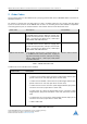
TMCM-1260 Hardware Manual • Hardware Version V1.10 | Document Revision V1.20 • 2018-05-17 Connector Connector type on-board Mating connector type USB USB-micro B female connector USB-micro B male connector I/O JST B8B-PH-K-S (JST PH series, 8pins, 2mm pitch) Connector housing: JST PHR-8 Contacts: JST SPH-002T-P0.5S Wire: 0.22mm2, AWG 24 9 / 30 Table 3: Connector Types and Mating Connectors of the TMCM-1260 4.
TMCM-1260 Hardware Manual • Hardware Version V1.10 | Document Revision V1.20 • 2018-05-17 4.2 10 / 30 Motor Connector Two four pin motor connectors are available. Either of them can be used for connecting a bipolar stepper motor. Both connectors are connected to the same driver stage therefore, just one connector should be used at the same time.
TMCM-1260 Hardware Manual • Hardware Version V1.10 | Document Revision V1.20 • 2018-05-17 Pin Label Direction 4 CAN_H Bidirectional CAN interface, diff. signal (non-inverting) 5 CAN_L Bidirectional CAN interface, diff. signal (inverting) 11 / 30 Description Table 6: RS485 + CAN Connector Pin Assignment 4.4 USB Connector For serial communication the TMCM-1260 offers selection between RS485, CAN and USB interfaces.
TMCM-1260 Hardware Manual • Hardware Version V1.10 | Document Revision V1.
TMCM-1260 Hardware Manual • Hardware Version V1.10 | Document Revision V1.20 • 2018-05-17 6 13 / 30 Reset to Factory Defaults It is possible to reset all settings in firmware for the TMCM-1260 to factory defaults without establishing a working communication connection. This might be helpful in case communication parameters of the preferred interface have been set to unknown values or got lost.
TMCM-1260 Hardware Manual • Hardware Version V1.10 | Document Revision V1.20 • 2018-05-17 14 / 30 7 I/Os The I/O connector (8pin JST PH series) offers one analog input, two non-isolated digital inputs with integrated pull-ups (programmable) and two optically isolated inputs. All inputs can be used for different purposes explained in more detail in the following subsections. 7.1 Analog input IN0 The TMCM-1260 offers one analog input. The analog input voltage range is approx. 0..+10V.
/ 30 TMCM-1260 Hardware Manual • Hardware Version V1.10 | Document Revision V1.20 • 2018-05-17 +5V microcontroller +5V...24V +3V3 +5V 2k2 or 10k IN1 IN2 or 22k microcontroller 33pF TMCM-1260 pull-up disabled pull-up enabled Figure 6: Digital inputs IN1 and IN2 7.3 HOME/STOP_L/STOP_R switch inputs The TMCM-1260 offers two optically isolated inputs which can be used as left (STOP_L) and right (STOP_R) stop switch inputs.
/ 30 TMCM-1260 Hardware Manual • Hardware Version V1.10 | Document Revision V1.20 • 2018-05-17 +5V microcontroller +3V3 +5V 2k2 ENC_A, ENC_B or 10k 22k microcontroller 33pF TMCM-1260 pull-up enabled Figure 8: External encoder input 7.5 Step/Direction inputs The TMCM-1260 may be used as driver with an external motion controller. In this case the Step/Direction output signals of the external motion controller may be connected to the optically isolated Step/Dir inputs of the TMCM-1260.
/ 30 TMCM-1260 Hardware Manual • Hardware Version V1.10 | Document Revision V1.20 • 2018-05-17 8 Communication 8.1 RS485 For remote control and communication with a host system the TMCM-1260 provides a two wire RS485 bus interface. For proper operation the following items should be taken into account when setting up an RS485 network: 1. BUS STRUCTURE: The network topology should follow a bus structure as closely as possible.
/ 30 TMCM-1260 Hardware Manual • Hardware Version V1.10 | Document Revision V1.
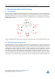
/ 30 TMCM-1260 Hardware Manual • Hardware Version V1.10 | Document Revision V1.20 • 2018-05-17 Host c:> Slave Slave Slave node 1 node n-1 node n } termination resistor (120 Ohm) CAN termination resistor (120 Ohm) keep distance as short as possible Figure 13: CAN bus structure with termination resistors 2. BUS TERMINATION: Especially for longer busses and/or multiple nodes connected to the bus and/or high communication speeds, the bus should be properly terminated at both ends.
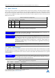
TMCM-1260 Hardware Manual • Hardware Version V1.10 | Document Revision V1.20 • 2018-05-17 9 20 / 30 Motor driver current The on-board stepper motor driver operates current controlled. The driver current may be programmed in software with 32 effective scaling steps in hardware. Explanation of different columns in table below: Motor current setting in software (TMCL) These are the values for TMCL axis parameter 6 (motor run current) and 7 (motor standby current).
TMCM-1260 Hardware Manual • Hardware Version V1.10 | Document Revision V1.20 • 2018-05-17 21 / 30 Motor current setting in software (TMCL) Current scaling step (CS) Motor current ICOIL [A] peak Motor current ICOIL [A] RMS 160. . . 167 20 5.332 3.770 168. . . 175 21 5.586 3.950 176. . . 183 22 5.840 4.129 184. . . 191 23 6.094 4.309 192. . . 199 24 6.348 4.488 200. . . 207 25 6.602 4.668 208. . . 215 26 6.855 4.848 216. . . 223 27 7.109 5.027 224. . . 231 28 7.363 5.
/ 30 TMCM-1260 Hardware Manual • Hardware Version V1.10 | Document Revision V1.20 • 2018-05-17 10 Functional Description The TMCM-1260 is a highly integrated single axis controller/driver module for stepper motors with up-to 6A RMS / 8.4A peak motor coil current. The TMCM-1260 can be controlled via RS485, CAN or USB serial interfaces. The TMCM-1260 comes with the PC based software development environment TMCL-IDE for the Trinamic Motion Control Language (TMCL™).
/ 30 TMCM-1260 Hardware Manual • Hardware Version V1.10 | Document Revision V1.20 • 2018-05-17 11 Operational Ratings and Characteristics NOTICE Never Exceed the absolute maximum ratings! Keep the power supply voltage below the upper limit of +54V! Otherwise the board electronics will seriously be damaged! Especially, when the selected operating voltage is near the upper limit a regulated power supply is highly recommended. General Operational Ratings Symbol Parameter Min Typ Max Unit 12 24.
/ 30 TMCM-1260 Hardware Manual • Hardware Version V1.10 | Document Revision V1.20 • 2018-05-17 Operational Ratings of the I/Os Symbol Parameter Min Typ Max Unit Table 12: Operational ratings of I/Os Operational Ratings of the RS485 Interface Symbol Parameter Min NRS485 Number of nodes connected to single RS485 network fRS485 Max.
TMCM-1260 Hardware Manual • Hardware Version V1.10 | Document Revision V1.20 • 2018-05-17 12 Abbreviations used in this Manual Abbreviation Description IDE Integrated Development Environment LED Light Emmitting Diode RMS Root Mean Square value TMCL TRINAMIC Motion Control Language Table 15: Abbreviations used in this Manual ©2018 TRINAMIC Motion Control GmbH & Co. KG, Hamburg, Germany Terms of delivery and rights to technical change reserved. Download newest version at www.trinamic.
TMCM-1260 Hardware Manual • Hardware Version V1.10 | Document Revision V1.20 • 2018-05-17 13 1 2 3 4 5 6 7 8 26 / 30 Figures Index Board dimensions, position of mounting holes and position (pin 1) of connectors (all values in mm) . . . . . . . TMCM-1260 connectors . . . . . . . . TMCM-1260 LEDs . . . . . . . . . . . . Reset to factory default settings . . . Analog input IN0 . . . . . . . . . . . . Digital inputs IN1 and IN2 . . . . . . . Stop switch inputs . . . . . . . . . . . External encoder input . .
TMCM-1260 Hardware Manual • Hardware Version V1.10 | Document Revision V1.20 • 2018-05-17 14 1 2 3 4 5 6 7 8 10 27 / 30 Tables Index TMCM-1260 Order Code . . . . . . . . TMCM-1260 Cable Loom . . . . . . . . Connector Types and Mating Connectors of the TMCM-1260 . . . . . . . . . Power Supply Connector Pin Assignment Motor Connector Pin Assignment . . RS485 + CAN Connector Pin Assignment USB Connector Pin Assignment . . . . I/O Connector Pin Assignment . . . . Available motor current settings . . .
TMCM-1260 Hardware Manual • Hardware Version V1.10 | Document Revision V1.20 • 2018-05-17 15 28 / 30 Supplemental Directives 15.1 Producer Information 15.2 Copyright TRINAMIC owns the content of this user manual in its entirety, including but not limited to pictures, logos, trademarks, and resources. © Copyright 2018 TRINAMIC. All rights reserved. Electronically published by TRINAMIC, Germany.
TMCM-1260 Hardware Manual • Hardware Version V1.10 | Document Revision V1.20 • 2018-05-17 29 / 30 or of any other nature are made hereunder with respect to information/specification or the products to which information refers and no guarantee with respect to compliance to the intended use is given. In particular, this also applies to the stated possible applications or areas of applications of the product.
TMCM-1260 Hardware Manual • Hardware Version V1.10 | Document Revision V1.20 • 2018-05-17 16 16.1 30 / 30 Revision History Hardware Revision Version Date Author Description V1.0 2017-OCT-30 GE Initial version V1.1 2018-FEB-21 GE Linear pre-regulator for driver supply added for better heat distribution on the pcb Table 16: Hardware Revision 16.2 Document Revision Version Date Author Description 1.00 2018-FEB-20 GE Initial version based on TMCM-1240 hardware manual 1.