
User Manual


CANopen Manual for TMCM-1140, TMCM-1160, and TMCM-1180 (Rev. 2.01 / 2017-JUL-26) 5
www.trinamic.com
8.1 Firmware Revision ............................................................................................................................................. 84
8.2 Document Revision ........................................................................................................................................... 84
9 References .................................................................................................................................................................... 85
Table of Figures
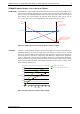
Figure 1.1 stallGuard2 load measurement SG as a function of load .................................................................... 8
Figure 1.2 Energy efficiency example with coolStep .................................................................................................. 8
Figure 2.1 Overview CANopen NMT state machine ................................................................................................... 10
Figure 2.2 Communication architecture ....................................................................................................................... 11
Figure 2.3 Device model ................................................................................................................................................... 12
Figure 3.1 Restore procedure .......................................................................................................................................... 18
Figure 4.1 Finite state machine ...................................................................................................................................... 30
Figure 4.2 Homing mode function ................................................................................................................................. 38
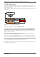
Figure 4.9 Multi-purpose I/O connector of TMCM-1140 ............................................................................................ 39
Figure 4.10 Multi-purpose I/O of TMCM-1160 .............................................................................................................. 40
Figure 4.11 I/O connectors of the TMCM-1180 ........................................................................................................... 42
Figure 4.3 Homing on negative switch and index pulse ........................................................................................ 44
Figure 4.4 Homing on positive limit switch and index pulse ............................................................................... 44
Figure 4.5 Homing on positive home switch and index pulse ............................................................................. 45
Figure 4.6 Homing on negative home switch and index pulse............................................................................ 45
Figure 4.7 Homing without index pulse ...................................................................................................................... 46
Figure 4.8 Homing on index pulse ................................................................................................................................ 46
Figure 4.12 Home offset definition ................................................................................................................................ 49
Figure 4.13 Transfer characteristic of the velocity acceleration ............................................................................ 55
Figure 5.1 Brake output timing ....................................................................................................................................... 63