
User Manual

CANopen Manual for TMCM-1140, TMCM-1160, and TMCM-1180 (Rev. 2.01 / 2017-JUL-26) 42
www.trinamic.com
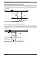
4.3.1.3 TMCM-1180
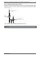
First of all it is necessary to connect the switches. A 2mm pitch 6 pin JST B6B-PH-K connector is used for
connecting general purpose inputs, home and stop switches to the unit.
Mating connector housing: PHR-6
Mating connector contacts: SPH-002T-P0.5S
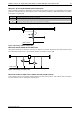
Input
and
switches
1
Output
1
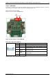
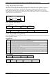
Figure 4.5 I/O connectors of the TMCM-1180
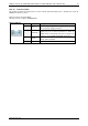
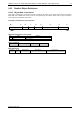
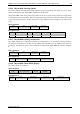
INPUT / STOP / HOME SWITCH CONNECTOR
1
6
Pin
Label
Description
1
IN_0
General purpose input, +24V compatible
2
IN_1
General purpose input, +24V compatible
3
STOP_L
Left stop switch input, +24V compatible, internal
pull-up (1k to +5V)
4
STOP_R
Right stop switch input, +24V compatible, internal
pull-up (1k to +5V)
5
HOME
Home switch input, +24V compatible, internal pull-
up (1k to +5V)
6
GND
Module ground (system and signal ground)
Table 4.1 Input / Stop / Home switch connector