
User Manual

CANopen Manual for TMCM-1140, TMCM-1160, and TMCM-1180 (Rev. 2.01 / 2017-JUL-26) 39
www.trinamic.com
4.3.1 Connecting Home Switch, Left Switch, and Right Switch
For detailed information refer to the specific hardware manual of your module!
4.3.1.1 TMCM-1140
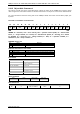
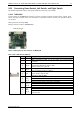
A 2mm pitch 8 pin JST B8B-PH-K connector is used for connecting general purpose inputs, outputs, home
switch, and stop switches to the unit. If desired it is possible to connect a brake, too. Therefore, OUT_O
can be used.
Mating connector housing: PHR-8
Mating connector contacts: SPH-002T-P0.5S
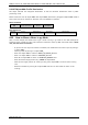
Multi-purpose I/O
1
Figure 4.3 Multi-purpose I/O connector of TMCM-1140
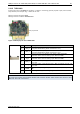
INPUT / STOP / HOME SWITCH CONNECTOR
8
1
Pin
Label
Description
1
GND
System and signal ground
2
VDD
VDD, connected to VDD pin of the power and communication
connector
3
OUT_0
Open-drain output (max. 1A)
Integrated freewheeling diode to VDD
Connect brake here if desired.
4
OUT_1
+5V supply output (max. 100mA)
Can be switched on/off in software
5
IN_0
Dedicated analog input,
Input voltage range: 0..+10V
Resolution: 12bit (0..4095)
6
IN_1,
STOP_L,
ENC_A
General purpose digital input (+24V compatible)
Alternate function 1: left stop switch input
Alternate function 2: external incremental encoder channel A input
7
IN_2,
STOP_R,
ENC_B
General purpose digital input (+24V compatible)
Alternate function 1: right stop switch input
Alternate function 2: external incremental encoder channel B input
8
IN_3,
HOME,
ENC_N
General purpose digital input (+24V compatible)
Alternate function 1: home switch input
Alternate function 2: external incremental encoder index / zero
channel input