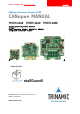
CANopen MODULES FOR STEPPER MOTORS CANopen Firmware Version V3.20 CANopen MANUAL TMCM-1140 TMCM-1160 TMCM-1180 1-Axis Controller/Driver Modules CANopen Motor Mountable (NEMA17, NEMA23/24, NEMA34) Integrated sensOstep™ Encoder UNIQUE FEATURES TRINAMIC Motion Control GmbH & Co. KG Hamburg, Germany www.trinamic.
CANopen Manual for TMCM-1140, TMCM-1160, and TMCM-1180 (Rev. 2.01 / 2017-JUL-26) Table of Contents 1 Preface ............................................................................................................................................................................. 6 1.1 General Features of the CANopen Implementation .................................................................................. 6 1.2 Abbreviations .......................................................................
CANopen Manual for TMCM-1140, TMCM-1160, and TMCM-1180 (Rev. 2.01 / 2017-JUL-26) 4.2.1.7 Object 6067h: Position Window .................................................................................................... 34 4.2.1.8 Object 6068h: Position Window Time.......................................................................................... 34 4.2.1.9 Object 606Ch: Velocity Actual Value ............................................................................................. 35 4.2.1.
CANopen Manual for TMCM-1140, TMCM-1160, and TMCM-1180 (Rev. 2.01 / 2017-JUL-26) 6 7 8 5.2.3 Object 2002h: Brake Delay Times ............................................................................................................ 63 5.2.4 Object 2003h: Maximum Current .............................................................................................................. 64 5.2.5 Object 2004h: Standby Current .......................................................................................
CANopen Manual for TMCM-1140, TMCM-1160, and TMCM-1180 (Rev. 2.01 / 2017-JUL-26) 8.1 Firmware Revision............................................................................................................................................. 84 8.2 Document Revision ........................................................................................................................................... 84 9 References .......................................................................................
CANopen Manual for TMCM-1140, TMCM-1160, and TMCM-1180 (Rev. 2.01 / 2017-JUL-26) 6 1 Preface This document specifies objects and modes of operation for the TMCM-1140, TMCM-1160, and TMCM-1180 with CANopen firmware. As these products are stepper motor controller and driver modules the use of the CiA DSP402 protocol (described in the CiA CANopen drives and motion control device profile, Part 2) is fundamental. The CANopen firmware is designed to fulfill the DS301 version 4.02 and DS402 version 3.
CANopen Manual for TMCM-1140, TMCM-1160, and TMCM-1180 (Rev. 2.01 / 2017-JUL-26) 7 1.
CANopen Manual for TMCM-1140, TMCM-1160, and TMCM-1180 (Rev. 2.01 / 2017-JUL-26) 8 TRINAMICS UNIQUE FEATURES – EASY TO USE WITH CANOPEN stallGuard2™ stallGuard2 is a high-precision sensorless load measurement using the back EMF on the coils. It can be used for stall detection as well as other uses at loads below those which stall the motor. The stallGuard2 measurement value changes linearly over a wide range of load, velocity, and current settings.
CANopen Manual for TMCM-1140, TMCM-1160, and TMCM-1180 (Rev. 2.01 / 2017-JUL-26) 9 2 Communication 2.1 Reference Model The application layer comprises a concept to configure and communicate real-time-data as well as the mechanisms for synchronization between devices. The functionality the application layer offers to an application is logically divided over different service data objects (SDO) in the application layer. A service object offers a specific functionality and all the related services.
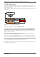
CANopen Manual for TMCM-1140, TMCM-1160, and TMCM-1180 (Rev. 2.01 / 2017-JUL-26) 10 2.2 NMT State Machine The finite state machine (FSM) or simply state machine is a model of behavior composed of a finite number of states, transitions between those states, and actions. It shows which way the logic runs when certain conditions are met. Starting and resetting the device is controlled via the state machine.
CANopen Manual for TMCM-1140, TMCM-1160, and TMCM-1180 (Rev. 2.01 / 2017-JUL-26) The Figure 2.2 shows the situation of the state machine in this device profile. CANopen device profile CiA DSP 402 Modes of operation: [used in this manual / according to CiA DSP 402] Homing mode Profile position mode Profile velocity mode Velocity mode Device control state machine CANopen Communication Profile CiA DS301 CAN Figure 2.2 Communication architecture www.trinamic.
CANopen Manual for TMCM-1140, TMCM-1160, and TMCM-1180 (Rev. 2.01 / 2017-JUL-26) 12 2.3 Device Model Following the device model, the device consists of three parts: communication, object dictionary, and application. Communication This function unit provides the communication objects and the appropriate functionality to transport data items via the underlying network structure.
CANopen Manual for TMCM-1140, TMCM-1160, and TMCM-1180 (Rev. 2.01 / 2017-JUL-26) 13 2.4 Object Dictionary The most important part of a device profile is the object dictionary description. The Object Dictionary is essentially a grouping of objects accessible via the network in an ordered pre-defined fashion. Each object within the dictionary is addressed using a 16-bit index.
CANopen Manual for TMCM-1140, TMCM-1160, and TMCM-1180 (Rev. 2.01 / 2017-JUL-26) 14 3 Communication Objects 3.1 Detailed Object Specifications 3.1.1 Object 1000h: Device Type This object contains information about the device type. The object 1000h describes the type of device and its functionality. It is composed of a 16-bit field which describes the device profile that is used and a second 16-bit field which gives additional information about optional functionality of the device.
CANopen Manual for TMCM-1140, TMCM-1160, and TMCM-1180 (Rev. 2.01 / 2017-JUL-26) 3.1.3 15 Object 1005h: COB-ID SYNC Message This object defines the COB-ID of the synchronization Object (SYNC). Further, it defines whether the module generates the SYNC. OBJECT DESCRIPTION Index 1005h Name COB-ID SYNC Message Object Code Variable Data Type UNSIGNED32 ENTRY DESCRIPTION Sub-Index Access rw 00h 3.1.
CANopen Manual for TMCM-1140, TMCM-1160, and TMCM-1180 (Rev. 2.01 / 2017-JUL-26) 3.1.7 16 Object 100Ch: Guard Time The objects at index 100Ch and 100Dh shall indicate the configured guard time respectively the life time factor. The life time factor multiplied with the guard time gives the life time for the life guarding protocol. OBJECT DESCRIPTION Index Name Guard time 100Ch Object Code Variable Data Type UNSIGNED16 ENTRY DESCRIPTION Sub-Index 00h 3.1.
CANopen Manual for TMCM-1140, TMCM-1160, and TMCM-1180 (Rev. 2.01 / 2017-JUL-26) 17 On read access to the appropriate sub-index the device provides information about its storage functionality with the following format.
CANopen Manual for TMCM-1140, TMCM-1160, and TMCM-1180 (Rev. 2.01 / 2017-JUL-26) 18 On reception of the correct signature in the appropriate sub-index the device restores the default parameters and then confirms the SDO transmission (initiate download response). If the restoring failed, the device responds with an Abort SDO Transfer (abort code: 0606 0000 h). If a wrong signature is written, the device refuses to restore the defaults and responds with an Abort SDO Transfer (abort code: 0800 002xh).
CANopen Manual for TMCM-1140, TMCM-1160, and TMCM-1180 (Rev. 2.01 / 2017-JUL-26) 19 3.1.11 Object 1014h: COB-ID Emergency Object This object defines the COB-ID of the emergency object (EMCY). OBJECT DESCRIPTION Index 1014h Name COB-ID emergency object Object Code Variable Data Type UNSIGNED32 ENTRY DESCRIPTION Sub-Index Access rw 00h PDO Mapping no Value Range UNSIGNED32 Default Value 80h + NODE ID 3.1.
CANopen Manual for TMCM-1140, TMCM-1160, and TMCM-1180 (Rev. 2.01 / 2017-JUL-26) 20 3.1.15 Object 1018h: Identity Object The object 1018h contains general information about the device. The Vendor ID (sub-index 01h) contains a unique value allocated to each manufacturer. The vendor ID of TRINAMIC is 0286h. The manufacturer-specific Product code (sub-index 2h) identifies a specific device version.
CANopen Manual for TMCM-1140, TMCM-1160, and TMCM-1180 (Rev. 2.01 / 2017-JUL-26) 21 3.1.18 Objects 1400h-1405h: Receive PDO Communication Parameter This object contains the communication parameters for the PDOs the device is able to receive. The subindex 0h contains the number of valid entries within the communication record. Its value is at least 2.
CANopen Manual for TMCM-1140, TMCM-1160, and TMCM-1180 (Rev. 2.01 / 2017-JUL-26) Sub-Index 03h Description Access Mapping entry 3 PDO Mapping rw no Value Range UNSIGNED32 22 Default Value Index Index Index Index Index 1600h: 1601h: 1602h: 1603h: 1605h: 0 0 0 0 0 3.1.20 Objects 1800h-1805h: Transmit PDO Communication Parameter These objects contain the communication parameters for the PDOs the device is able to transmit.
CANopen Manual for TMCM-1140, TMCM-1160, and TMCM-1180 (Rev. 2.01 / 2017-JUL-26) 3.1.21 Objects 1A00h-1A05h: Transmit PDO Mapping Parameter These objects contain the mapping for the PDOs the device is able to transmit.
CANopen Manual for TMCM-1140, TMCM-1160, and TMCM-1180 (Rev. 2.01 / 2017-JUL-26) 24 4 Device Profile Objects (CiA402) and Modes of Operation The PDS (power drive system) behavior depends on the activated mode of operation. The PDS implements several modes of operation. Since it is not possible to operate the modes in parallel, the user is able to activate the required function by selecting a mode of operation.
CANopen Manual for TMCM-1140, TMCM-1160, and TMCM-1180 (Rev. 2.01 / 2017-JUL-26) 4.1.2 25 Object 605Bh: Shutdown Option Code This object indicates what action is performed if there is a transition from operation enabled state to ready to switch on state. The shutdown option code always has the value 0 as only this is supported.
CANopen Manual for TMCM-1140, TMCM-1160, and TMCM-1180 (Rev. 2.01 / 2017-JUL-26) 4.1.5 26 Object 605Eh: Fault Reaction Option Code This object indicates what action is performed when fault is detected in the power drive system. The slow down ramp is the deceleration value of the used mode of operation. The fault reaction option code always has the value 2 as only this is supported.
CANopen Manual for TMCM-1140, TMCM-1160, and TMCM-1180 (Rev. 2.01 / 2017-JUL-26) 4.1.8 27 Object 606Ah: Sensor Selection Code This object provides the source of the velocity sensor actual value. It selects whether an encoder is to be used or not. VALUE DEFINITION Value 0 -1 Definition Encoder used No encoder OBJECT DESCRIPTION Index Name Sensor selection code 606Ah Object Code Variable Data Type SIGNED16 ENTRY DESCRIPTION Sub-Index Access rw 00h 4.1.
CANopen Manual for TMCM-1140, TMCM-1160, and TMCM-1180 (Rev. 2.01 / 2017-JUL-26) 28 4.1.11 Object 60C5h: Max Acceleration This object indicates the configured maximaum acceleration. It is used to limit the acceleration to an acceptable value in order to prevent the motor and the moved mechanics from being destroyed. It is given in internal or user specific units (depending on object 208C h, paragraph 0, object 2087h and object 2088h, paragraph 0 and paragraph 5.2.
CANopen Manual for TMCM-1140, TMCM-1160, and TMCM-1180 (Rev. 2.01 / 2017-JUL-26) 29 4.1.
CANopen Manual for TMCM-1140, TMCM-1160, and TMCM-1180 (Rev. 2.01 / 2017-JUL-26) 30 4.2 Profile Position Mode A target position is applied to the trajectory generator. It is generating a position-demand-value for the position control loop described in the position control function. Please refer to object 6060h (section 4.1.6) for information about how to choose an operation mode. Object 6061 h (section 4.1.7) shows the operation mode that is set. 4.2.
CANopen Manual for TMCM-1140, TMCM-1160, and TMCM-1180 (Rev. 2.01 / 2017-JUL-26) 31 4.2.1.1 Object 6040h: Controlword This object indicates the received command controlling the power drive system finite state automation (PDS FSA). The CiA-402 state machine can be controlled using this object. Please refer to Figure 4.1 Finite state machine for detailed information.
CANopen Manual for TMCM-1140, TMCM-1160, and TMCM-1180 (Rev. 2.01 / 2017-JUL-26) 32 4.2.1.2 Object 6041h: Statusword This object provides the status of the PDS FSA. It reflects the status of the CiA402 state machine. Please refer to Figure 4.1 Finite state machine for detailed information. The object is structured as defined below. For more information about the coding refer to the CANopen Drives and motion control device profile, part 2 please.
CANopen Manual for TMCM-1140, TMCM-1160, and TMCM-1180 (Rev. 2.01 / 2017-JUL-26) 33 4.2.1.3 Object 6062h: Position Demand Value This object provides the demanded position value. The value is given in microsteps. Object 6062h indicates the actual position that the motor should have. It is not to be confused with the objects 6063h and 6064h.
CANopen Manual for TMCM-1140, TMCM-1160, and TMCM-1180 (Rev. 2.01 / 2017-JUL-26) 34 4.2.1.6 Object 6065h: Following Error Window This object indicates the configured range of tolerated position values symmetrically to the position demand value. If the position actual value is out of the following error window, a following error occurs. A following error may occur when a drive is blocked, unreachable profile velocity occurs, or at wrong closed-loop coefficients. The value shall is in microsteps.
CANopen Manual for TMCM-1140, TMCM-1160, and TMCM-1180 (Rev. 2.01 / 2017-JUL-26) 35 4.2.1.9 Object 606Ch: Velocity Actual Value This object gives the actual velocity value derived either from the velocity sensor or from the position sensor. OBJECT DESCRIPTION Index Name Velocity actual value 606Ch Object Code Variable Data Type INTEGER32 ENTRY DESCRIPTION Sub-Index Access ro 00h PDO Mapping Refer to CiA402-3 Value Range INTEGER32 Default Value no 4.2.1.
CANopen Manual for TMCM-1140, TMCM-1160, and TMCM-1180 (Rev. 2.01 / 2017-JUL-26) 36 4.2.1.12 Object 607Fh: Maximum Profile Velocity This object indicates the configured maximal allowed velocity in either direction during a profiled motion. It is the maximum velocity that can be used for positioning. The value is given in internal or user specific units (depending on object 208Ch, paragraph 0).
CANopen Manual for TMCM-1140, TMCM-1160, and TMCM-1180 (Rev. 2.01 / 2017-JUL-26) 37 4.2.1.15 Object 6084h: Profile Deceleration This object indicates the configured deceleration. It sets the maximum deceleration used in profile positioning mode. Please choose the units for object 6084h with object 208Eh, described in paragraph 0. Object 208Eh reads 0 when internal units are selected or 179 when user units (PPS/s) are selected.
CANopen Manual for TMCM-1140, TMCM-1160, and TMCM-1180 (Rev. 2.01 / 2017-JUL-26) 38 4.3 Homing Mode This clause describes the method by which a drive seeks the home position (reference point). There are various methods of achieving this using limit switches at the ends of travel or a home switch in midtravel. Some methods also use the index (zero) pulse train from an incremental encoder. The user may specify the speeds, acceleration and the method of homing.
CANopen Manual for TMCM-1140, TMCM-1160, and TMCM-1180 (Rev. 2.01 / 2017-JUL-26) 4.3.1 39 Connecting Home Switch, Left Switch, and Right Switch For detailed information refer to the specific hardware manual of your module! 4.3.1.1 TMCM-1140 A 2mm pitch 8 pin JST B8B-PH-K connector is used for connecting general purpose inputs, outputs, home switch, and stop switches to the unit. If desired it is possible to connect a brake, too. Therefore, OUT_O can be used.
CANopen Manual for TMCM-1140, TMCM-1160, and TMCM-1180 (Rev. 2.01 / 2017-JUL-26) 40 4.3.1.2 TMCM-1160 A 2mm pitch 8-pin JST B8B-PH-K connector is used for connecting general purpose inputs, home switch, stop switches, and outputs (e.g. a brake) to the unit. Mating connector housing: PHR-8 Mating connector contacts: SPH-002T-P0.5S Multi-purpose I/O 1 Figure 4.
CANopen Manual for TMCM-1140, TMCM-1160, and TMCM-1180 (Rev. 2.01 / 2017-JUL-26) 4.3.1.2.1 41 Digital Inputs STOP_L, STOP_R, and HOME The eight pin connector of the TMCM-1160 provides three reference switch digital inputs STOP_L, STOP_R and HOME. All three inputs accept up to +24 V input signals. They are protected against these higher voltages using voltage resistor dividers together with limiting diodes against voltages below 0 V (GND) and above +3.3 V DC.
CANopen Manual for TMCM-1140, TMCM-1160, and TMCM-1180 (Rev. 2.01 / 2017-JUL-26) 42 4.3.1.3 TMCM-1180 First of all it is necessary to connect the switches. A 2mm pitch 6 pin JST B6B-PH-K connector is used for connecting general purpose inputs, home and stop switches to the unit. Mating connector housing: PHR-6 Mating connector contacts: SPH-002T-P0.5S Input and switches Output 1 1 Figure 4.
CANopen Manual for TMCM-1140, TMCM-1160, and TMCM-1180 (Rev. 2.01 / 2017-JUL-26) 4.3.1.3.1 43 Connect a Brake The module provides the opportunity to connect a brake. Please take OUT_1 for it. A 2mm pitch 4 pin JST B4B-PH-K connector is used. Mating connector housing: PHR-4 Mating connector contacts: SPH-002T-P0.5S OUTPUT CONNECTOR 1 4 www.trinamic.
CANopen Manual for TMCM-1140, TMCM-1160, and TMCM-1180 (Rev. 2.01 / 2017-JUL-26) 4.3.2 44 Homing Methods There are several different methods of homing. For choosing your homing method, refer to object 6098h please. OVERVIEW: HOMING METHODS Method no. 0 1 2 3 5 17 18 19 21 33 34 35 Description No homing. This is the default setting. Search the left end switch, than search the next encoder index pulse. Search the right end switch, than search the next encoder index pulse.
CANopen Manual for TMCM-1140, TMCM-1160, and TMCM-1180 (Rev. 2.01 / 2017-JUL-26) 45 METHOD 3: HOMING ON POSITIVE HOME SWITCH AND INDEX PULSE Using this method, the initial direction of movement shall be dependent on the state of the home switch. The home position shall be at the index pulse to either to the left or the right of the point where the home switch changes state.
CANopen Manual for TMCM-1140, TMCM-1160, and TMCM-1180 (Rev. 2.01 / 2017-JUL-26) 46 METHOD 17, 18, 19, AND 21: HOMING WITHOUT INDEX PULSE These methods are similar to methods 1 to 5 except that the home position is not dependent on the index pulse but only dependent on the relevant home or limit switch transitions. Method 19 (similar to method 3) is shown in Figure 4.10. Method no. 17 18 19 21 Description Search the left end switch. (Similar to method 1) Search the right end switch.
CANopen Manual for TMCM-1140, TMCM-1160, and TMCM-1180 (Rev. 2.01 / 2017-JUL-26) 4.3.3 47 Detailed Object Definitions 4.3.3.1 Object 6040h: Controlword This object indicates the received command controlling the power drive system finite state automation (PDS FSA). The CiA-402 state machine can be controlled using this object. Please refer to Figure 4.1 Finite state machine for detailed information. STRUCTURE OF CONTROLWORD / VALUE DEFINITION 15 9 see 4.2.1.1 7 8 Halt 6 5 4 see 4.2.1.
CANopen Manual for TMCM-1140, TMCM-1160, and TMCM-1180 (Rev. 2.01 / 2017-JUL-26) 48 4.3.3.2 Object 6041h: Statusword This object provides the status of the PDS FSA. It reflects the status of the CiA402 state machine. Please refer to Figure 4.1 Finite state machine for detailed information. The object is structured as defined below. For more information about the coding refer to the CANopen Drives and motion control device profile, part 2 please. STRUCTURE OF STATUSWORD / VALUE DEFINITION 15 14 see 4.2.
CANopen Manual for TMCM-1140, TMCM-1160, and TMCM-1180 (Rev. 2.01 / 2017-JUL-26) 49 4.3.3.4 Object 607Ch: Home Offset This object indicates the configured difference between the zero position for the application and the machine home position/home switch (found during homing). While homing, the machine home position is found and once the homing is completed, the zero position is offset from the home position by adding the home offset to the home position.
CANopen Manual for TMCM-1140, TMCM-1160, and TMCM-1180 (Rev. 2.01 / 2017-JUL-26) 50 4.3.3.6 Object 6099h: Homing Speeds This object indicates the configured speeds used during homing procedure. The values are given in units, which can be selected with object 208Ch, described in paragraph 0. Using object 6099h a fast and a slow homing speed can be set. In most homing modes, the home switch is searched with the fast speed first.
CANopen Manual for TMCM-1140, TMCM-1160, and TMCM-1180 (Rev. 2.01 / 2017-JUL-26) 4.3.4 51 How to Start a Homing in hm Mode Here is a little example that shows how to home the motor in hm mode. In this little example we assume that the module has been reset (and then switched to start) by NMT commands before. The home switch must be connected to the home switch input. It can be operated manually. - Select hm mode by writing 6 to object 6060h.
CANopen Manual for TMCM-1140, TMCM-1160, and TMCM-1180 (Rev. 2.01 / 2017-JUL-26) 52 4.4 Velocity Mode The velocity mode is used to control the velocity of the drive without a special regard of the position. It contains limit functions. THE OPERATION OF THE REFERENCE VALUE GENERATOR AND THE INPUT PARAMETERS INCLUDE: - Velocity Acceleration Deceleration Emergency stop Please refer to object 6060h (section 4.1.6) for information about how to choose an operation mode. Object 6061 h (section 4.1.
CANopen Manual for TMCM-1140, TMCM-1160, and TMCM-1180 (Rev. 2.01 / 2017-JUL-26) 53 4.4.1.2 Object 6041h: Statusword This object provides the status of the PDS FSA. It reflects the status of the CiA402 state machine. Please refer to Figure 4.1 Finite state machine for detailed information. The object is structured as defined below. For more information about the coding refer to the CANopen Drives and motion control device profile, part 2 please. STRUCTURE OF STATUSWORD / VALUE DEFINITION 15 14 see 4.2.1.
CANopen Manual for TMCM-1140, TMCM-1160, and TMCM-1180 (Rev. 2.01 / 2017-JUL-26) 54 4.4.1.4 Object 6043h: vl Velocity Demand The object provides the instantaneous velocity generated by the ramp function. It shows the last target velocity that has been set using object 6042h. The value is given in the same unit as the target velocity, too. Please refer to object 208Ch (paragraph 0) for more information about that.
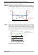
CANopen Manual for TMCM-1140, TMCM-1160, and TMCM-1180 (Rev. 2.01 / 2017-JUL-26) 55 4.4.1.7 Object 6048h: vl Velocity Acceleration This object indicates the configured delta speed and delta time of the slope of the acceleration ramp as shown in the following figure. Object 6048h provides the acceleration used in velocity mode. This value is also used for the deceleration. The value of the delta speed is given in internal or in user units (rpm/s).
CANopen Manual for TMCM-1140, TMCM-1160, and TMCM-1180 (Rev. 2.01 / 2017-JUL-26) 56 4.5 Profile Velocity Mode The profile velocity mode is used to control the velocity of the drive without a special regard of the position. It contains limit functions and trajectory generation.
CANopen Manual for TMCM-1140, TMCM-1160, and TMCM-1180 (Rev. 2.01 / 2017-JUL-26) 57 4.5.1.2 Object 6041h: Statusword This object provides the status of the PDS FSA. It reflects the status of the CiA402 state machine. Please refer to Figure 4.1 Finite state machine for detailed information. The object is structured as defined below. For more information about the coding refer to the CANopen Drives and motion control device profile, part 2 please. STRUCTURE OF STATUSWORD / VALUE DEFINITION 15 14 see 4.2.1.
CANopen Manual for TMCM-1140, TMCM-1160, and TMCM-1180 (Rev. 2.01 / 2017-JUL-26) 58 4.5.1.5 Object 6064h: Position Actual Value This object provides the actual value of the position measurement device. It always contains the same value as object 6063h. The value is given in microsteps. OBJECT DESCRIPTION Index 6064h Name Position actual value Object Code Variable Data Type SIGNED32 ENTRY DESCRIPTION Sub-Index Access ro 00h PDO Mapping Refer to CiA402-3 Value Range SIGNED32 Default Value No 4.5.
CANopen Manual for TMCM-1140, TMCM-1160, and TMCM-1180 (Rev. 2.01 / 2017-JUL-26) 59 4.5.1.8 Object 607Dh: Software Position Limit This object indicates the configured maximal and minimal software position limits. These parameters define the absolute position limits for the position demand value and the position actual value. The position actual vale is always checked against these limits. The limit position is always relative to the machine home position.
CANopen Manual for TMCM-1140, TMCM-1160, and TMCM-1180 (Rev. 2.01 / 2017-JUL-26) 60 4.5.1.11 Object 60FFh: Target Velocity This object indicates the configured target velocity and is used as input for the trajectory generator. Object 60FFh sets the target velocity when using profile velocity mode. The drive then accelerates or decelerates to that velocity using the acceleration and deceleration set by objects 6083 h and 6084h.
CANopen Manual for TMCM-1140, TMCM-1160, and TMCM-1180 (Rev. 2.01 / 2017-JUL-26) 61 5 Manufacturer Specific Area The manufacturer segment contains manufacturer specific objects. These objects control special features of the TRINAMIC motion control devices TMCM-1180, TMCM-1160, and TMCM-1140. 5.1 coolStep™ related Objects (Overview) The figure below gives an overview of the coolStep related objects. Please have in mind that the figure shows only one example for a drive.
CANopen Manual for TMCM-1140, TMCM-1160, and TMCM-1180 (Rev. 2.01 / 2017-JUL-26) 62 COOLSTEP RELATED OBJECTS Note: smartEnergy is an earlier name for coolStep Object Name Description Sets the lower motor current limit for coolStep operation by scaling the CS (current Scale, see object 2003h) value.
CANopen Manual for TMCM-1140, TMCM-1160, and TMCM-1180 (Rev. 2.01 / 2017-JUL-26) 63 5.2 Detailed Object Specifications 5.2.1 Object 2000h: Microstep Resolution This object sets the microstep resolution of the drive. A value of 6 means 64 microsteps (26). It is only writeable in the SWITCHED_ON_DISABLED state, but always readable.
CANopen Manual for TMCM-1140, TMCM-1160, and TMCM-1180 (Rev. 2.01 / 2017-JUL-26) 64 OBJECT DESCRIPTION Index Name Brake delay times 2002h Object Code ARRAY Data Type UNSIGNED16 ENTRY DESCRIPTION Sub-Index Description Time between applying brake / disabling power stage Time between releasing brake / switching the state machine to operational 01h 02h 5.2.
CANopen Manual for TMCM-1140, TMCM-1160, and TMCM-1180 (Rev. 2.01 / 2017-JUL-26) 5.2.7 65 Object 200Ah: Enable Drive Delay Time This is an additional delay time (in milliseconds) between enabling the power stage and releasing the brake. It can be used to prevent the brake from being released too early (before the hold current in the motor has been reached). Please see also object 2002h.
CANopen Manual for TMCM-1140, TMCM-1160, and TMCM-1180 (Rev. 2.01 / 2017-JUL-26) 66 5.2.10 Object 204Eh: Boost Current This object is used to set the current used for acceleration and deceleration phases. If set to 0 the current set with object 2003h (maximum current setting) will be used. The value 1 can be chosen for a minimum boost current setting. A value of 255 means 100% of the maximum possible current of the module (this depends on the module type).
CANopen Manual for TMCM-1140, TMCM-1160, and TMCM-1180 (Rev. 2.01 / 2017-JUL-26) 67 5.2.13 Object 2087h: Maximum Velocity The functionality of this object depends on the unit selection (refer to object 208Ch / chapter 0): - If internal units are selected this object will be set to the fixed value of 2047 and cannot be changed. If user units are selected the maximum velocity (RPM or PPS) that is to be used must be set here. A lower value in this object leads to a better accuracy of the unit conversion.
CANopen Manual for TMCM-1140, TMCM-1160, and TMCM-1180 (Rev. 2.01 / 2017-JUL-26) 68 5.2.16 Object 208Ch: Velocity Dimension Index With this object different units can be chosen: - Writing 0 selects internal units. Writing 164 sets RPM for velocity and RPM/s for acceleration. Writing 181 sets PPS for velocity and PPS/s for acceleration. This can only be changed in SWITCHED_ON_DISABLED mode.
CANopen Manual for TMCM-1140, TMCM-1160, and TMCM-1180 (Rev. 2.01 / 2017-JUL-26) 69 5.2.19 Object 2093h: Chopper Mode Select the chopper mode with this object: 0 – spreadCycle™ chopper 1 – classic const. off time chopper OBJECT DESCRIPTION Index Name Chopper mode 2093h Object Code Variable Data Type UNSIGNED8 ENTRY DESCRIPTION Sub-Index Access rw 00h PDO Mapping no Value Range 0/1 Default Value 0 5.2.
CANopen Manual for TMCM-1140, TMCM-1160, and TMCM-1180 (Rev. 2.01 / 2017-JUL-26) 70 5.2.22 Object 2096h: Chopper Hysteresis Start This object provides the hysteresis start setting. Please remark, that this value is an offset to the hysteresis end value. OBJECT DESCRIPTION Index 2096h Name Chopper hysteresis start Object Code Variable Data Type UNSIGNED8 ENTRY DESCRIPTION Sub-Index Access rw 00h PDO Mapping no Value Range 0… 8 Default Value 3 5.2.
CANopen Manual for TMCM-1140, TMCM-1160, and TMCM-1180 (Rev. 2.01 / 2017-JUL-26) 71 5.2.25 Object 2099h: Smart Energy Current down Step This object provides the setting of the number of stallGuard2™ readings above the upper threshold necessary for each current decrement of the motor current.
CANopen Manual for TMCM-1140, TMCM-1160, and TMCM-1180 (Rev. 2.01 / 2017-JUL-26) 72 5.2.28 Object 209Ch: Smart Energy Hysteresis Start This object serves to set the lower threshold for the stallGuard2 value (see smart Energy current up step above). OBJECT DESCRIPTION Index 209Ch Name Smart energy hysteresis start Object Code Variable Data Type UNSIGNED8 ENTRY DESCRIPTION Sub-Index Access rw 00h PDO Mapping no Value Range 0… 15 Default Value 0 5.2.
CANopen Manual for TMCM-1140, TMCM-1160, and TMCM-1180 (Rev. 2.01 / 2017-JUL-26) 5.2.31 Object 209Fh: Slope Control High Side This object determines the slope of the motor driver outputs. 0 – lowest slope 3 – fastest slope OBJECT DESCRIPTION Index 209Fh Name Slope control high side Object Code Variable Data Type UNSIGNED8 ENTRY DESCRIPTION Sub-Index Access rw 00h PDO Mapping no Value Range 0… 3 Default Value 3 5.2.
CANopen Manual for TMCM-1140, TMCM-1160, and TMCM-1180 (Rev. 2.01 / 2017-JUL-26) 74 5.2.34 Object 20A2h: Short Detection Timer This object provides the timing of the short detection. Use default value! Value 0 1 2 3 Timing 3.2µs 1.6µs 1.2µs 0.8µs OBJECT DESCRIPTION Index 20A2h Name Short detection timer Object Code Variable Data Type UNSIGNED8 ENTRY DESCRIPTION Sub-Index Access rw 00h PDO Mapping no Value Range 0… 3 Default Value 0 5.2.
CANopen Manual for TMCM-1140, TMCM-1160, and TMCM-1180 (Rev. 2.01 / 2017-JUL-26) 75 5.2.38 Object 20A6h: Smart Energy Slow Run Current This object can be used for setting the motor current below the threshold speed. OBJECT DESCRIPTION Index 20A6h Name Smart energy slow run current Object Code Variable Data Type UNSIGNED8 ENTRY DESCRIPTION Sub-Index Access PDO Mapping rw 00h Value Range max.module current 0… 255 [ no 255 Default Value ] 0 5.2.
CANopen Manual for TMCM-1140, TMCM-1160, and TMCM-1180 (Rev. 2.01 / 2017-JUL-26) 76 5.2.42 Object 2103h: Pulse Divisor Display The pulse divisor display shows the pulse divisor that has been calculated by the drive when user units are selected or that can be set using object 2086h when internal units are selected.
CANopen Manual for TMCM-1140, TMCM-1160, and TMCM-1180 (Rev. 2.01 / 2017-JUL-26) 77 5.2.46 Object 2107h: Microstep Resolution Display This object shows the microstep resolution (set by object 2000h when internal units are selected or calculated when user units are selected). OBJECT DESCRIPTION Index Name Microstep resolution display 2107h Object Code Variable Data Type UNSIGNED8 ENTRY DESCRIPTION Sub-Index Access ro 00h PDO Mapping no Value Range 0… 8 Default Value 6 5.2.
CANopen Manual for TMCM-1140, TMCM-1160, and TMCM-1180 (Rev. 2.01 / 2017-JUL-26) 78 5.2.49 Object 2702h: Digital Inputs Bits 16… 23 of this object reflect the states of the digital inputs of the module. Bit 16 17 18 19 etc. Input IN_O IN_1 IN_2 IN_3 OBJECT DESCRIPTION Index Name Digital inputs 2702h Object Code Variable Data Type UNSIGNED32 ENTRY DESCRIPTION Sub-Index Access ro 00h PDO Mapping no Value Range - Default Value 0 5.2.
CANopen Manual for TMCM-1140, TMCM-1160, and TMCM-1180 (Rev. 2.01 / 2017-JUL-26) 79 5.2.52 Object 2705h: Node ID On modules that do not have address switches the node ID can be selected using this object. On modules with address switches the node ID is normally selected using the address switches. Only when the address switches are set to an invalid value (0 or >127) this object overrides the address switch setting. To change the node ID, first write the new node ID to this object.
CANopen Manual for TMCM-1140, TMCM-1160, and TMCM-1180 (Rev. 2.01 / 2017-JUL-26) 80 5.2.55 Object 2708h: Node ID Load This object shows the selected node ID. OBJECT DESCRIPTION Index Name Node ID 2708h Object Code Variable Data Type UNSIGNED8 ENTRY DESCRIPTION Sub-Index Access ro 00h PDO Mapping no Value Range 1… 127 Default Value Depends on ID switches 5.2.56 Object 270Eh: Device Analogue Inputs This object defines the analog inputs that can be used.
CANopen Manual for TMCM-1140, TMCM-1160, and TMCM-1180 (Rev. 2.01 / 2017-JUL-26) 5.2.1 81 Object 2710h: Pull-up Resistors This object switches the pull-up resistors of the inputs on or off. TMCM-1140: All pull-up can be switched by bit 0 (0=off, 1=on). TMCM-1160, TMCM-1180: Bit 0 pull-up resistor for stop left input, bit 1 switches pull-up resistor for stop right input, and bit 2 switches pull-up resistor for home input.
CANopen Manual for TMCM-1140, TMCM-1160, and TMCM-1180 (Rev. 2.01 / 2017-JUL-26) Error code Add. byte Description 1 2 3 4 5 0x81110 2 255 0 0 0 CAN Tx buffer overflow The software CAN transmit buffer is full and thus some CAN messages are lost. 0x81110 3 255 0 0 0 CAN Rx buffer overflow The software CAN receive buffer is full and so some CAN messages are lost.
CANopen Manual for TMCM-1140, TMCM-1160, and TMCM-1180 (Rev. 2.01 / 2017-JUL-26) 7 Life Support Policy TRINAMIC Motion Control GmbH & Co. KG does not authorize or warrant any of its products for use in life support systems, without the specific written consent of TRINAMIC Motion Control GmbH & Co. KG.
CANopen Manual for TMCM-1140, TMCM-1160, and TMCM-1180 (Rev. 2.01 / 2017-JUL-26) 84 8 Revision History 8.1 Firmware Revision Version 3.05 3.16 3.
CANopen Manual for TMCM-1140, TMCM-1160, and TMCM-1180 (Rev. 2.01 / 2017-JUL-26) 9 References [TMCM-1180 / PD-1180] [TMCM-1160 / PD-1160] [TMCM-1140 / PD-1140] www.trinamic.