
User Manual


Table Of Contents
- 1 Features
- 2 Order Codes
- 3 Mechanical and Electrical Interfacing
- 4 Connectors
- 5 Jumper Settings
- 6 LEDs
- 7 Communication
- 8 Functional Description
- 9 Operational Ratings and Characteristics
- 10 Abbreviations used in this Manual
- 11 Figures Index
- 12 Tables Index
- 13 Supplemental Directives
- 14 Revision History
TMCM-1110 Hardware Manual • Hardware Version V2.30 | Document Revision V1.10 • 2017-SEP-06
9 / 26
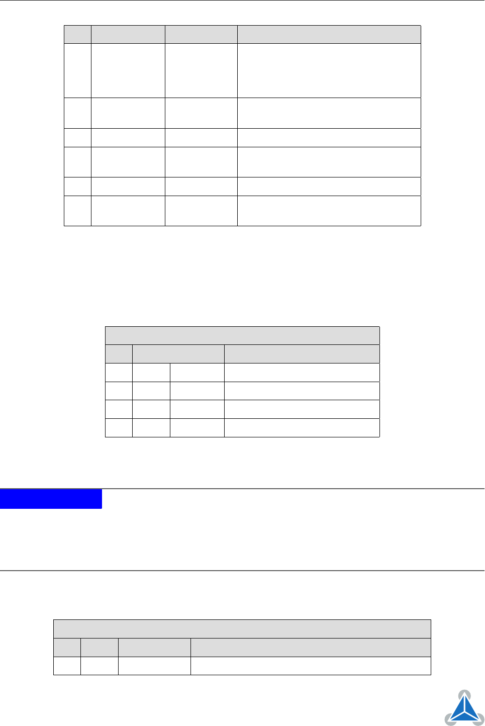
Pin Label Direction Description
9 AIN_0 in
Analog input (can be used as home
switch).
Input voltage range: 0. . . +10V
Resolution: 12bit (0. . . 4095)
10 PHASE_A in
Encoder input channel A (+5V compat-
ible, internal pull-up to +5V)
11 OpenDrain_1 out Open-drain output (max. 100mA)
12 PHASE_B in
Encoder input channel B (+5V compat-
ible, internal pull-up to +5V)
13 OpenDrain_2 out Open-drain output (max. 100mA)
14 PHASE_Z in
Encoder input zero channel (+5V com-
patible, internal pull-up to +5V)
Table 4: I/O Connector Pin Assignment
4.3 Motor Connector
The motor has to be connected to the motor connector, one phase (phase A) between A1 and A2 and the
second phase (phase B) between B1 and B2.
Motor Connector Pin Assignment
Pin Label Direction Description
1 A1 out Pin 1 of motor coil A
2 A2 out Pin 2 of motor coil A
3 B1 out Pin 1 of motor coil B
4 B2 out Pin 2 of motor coil B
Table 5: Motor Connector Pin Assignment
NOTICE
Do not connect or disconnect motor during operation!
Motor cable and mo-
tor inductivity might lead to voltage spikes when the motor is (dis)connected
while energized. These voltage spikes might exceed voltage limits of the driver
MOSFETs and might permanently damage them. Therefore, always switch off
/ disconnect power supply or at least disable driver stage before connecting /
disconnecting motor.
4.4 Reference Switch Connector (TMC429)
Reference Switch Connector Pin Assignment
Pin Label Direction Description
1 GND Power (GND) Signal and system ground
©2017 TRINAMIC Motion Control GmbH & Co. KG, Hamburg, Germany
Terms of delivery and rights to technical change reserved.
Download newest version at www.trinamic.com