
User Manual


Table Of Contents
- 1 Features
- 2 Order Codes
- 3 Mechanical and Electrical Interfacing
- 4 Connectors
- 5 Jumper Settings
- 6 LEDs
- 7 Communication
- 8 Functional Description
- 9 Operational Ratings and Characteristics
- 10 Abbreviations used in this Manual
- 11 Figures Index
- 12 Tables Index
- 13 Supplemental Directives
- 14 Revision History
TMCM-1110 Hardware Manual • Hardware Version V2.30 | Document Revision V1.10 • 2017-SEP-06
8 / 26
4.1 Power Connector
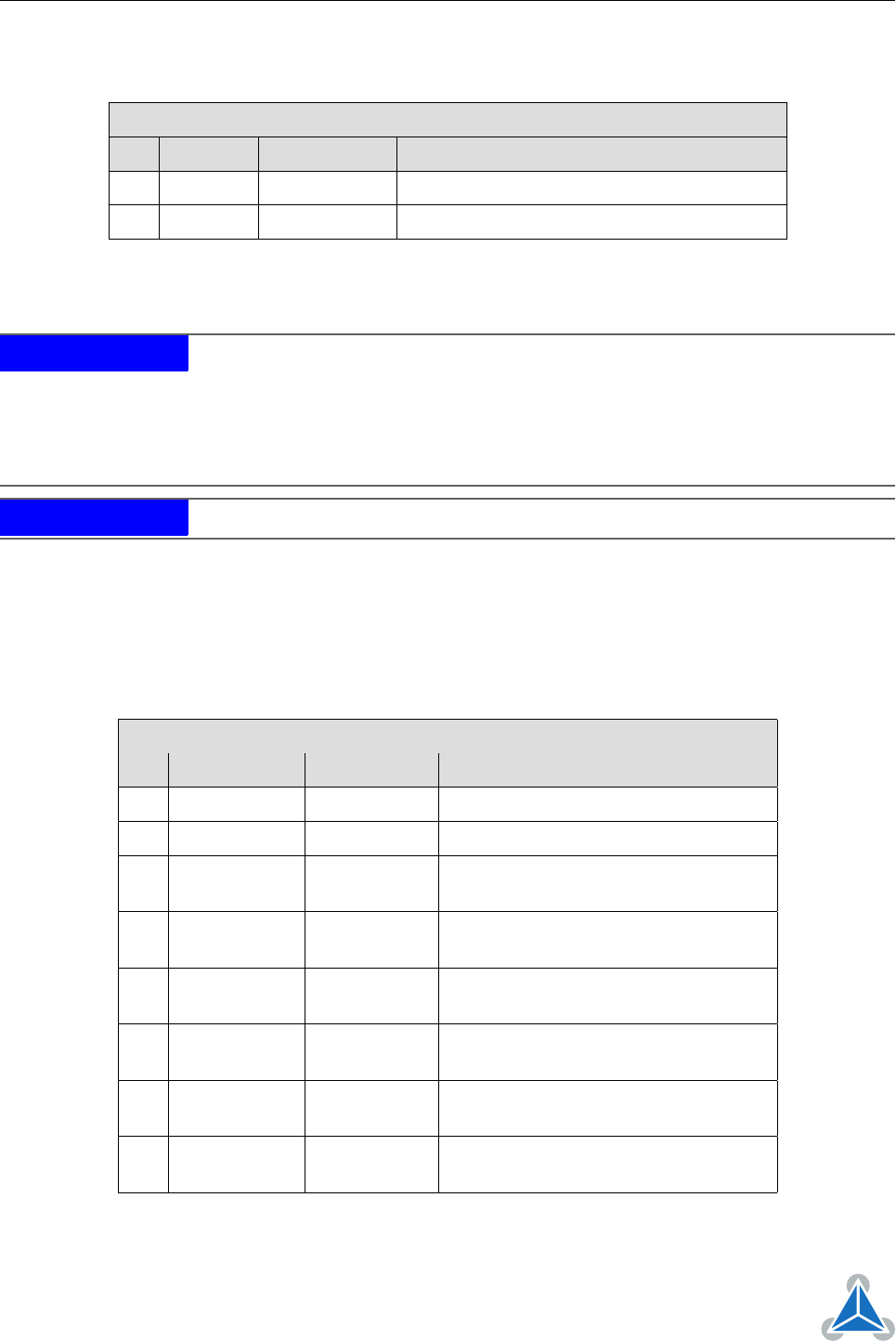
Power Supply Connector Pin Assigment
Pin Label Direction Description
1 GND Power (GND) Common system supply and signal ground
2 10. . . 30V Power (input) Power supply voltage
Table 3: Power Supply Connector Pin Assignment
NOTICE
Do not connect or disconnect motor during operation!
Motor cable and mo-
tor inductivity might lead to voltage spikes when the motor is (dis)connected
while energized. These voltage spikes might exceed voltage limits of the driver
MOSFETs and might permanently damage them. Therefore, always switch off
/ disconnect power supply or at least disable driver stage before connecting /
disconnecting motor.
NOTICE
Take care of polarity, wrong polarity can destroy the board!
4.2 I/O Connector (Microcontroller)
The TMCM-1110_V23 offers an on-board ARM Cortex-M4
™
microcontroller with +3V3 powered IOs and
+5V tolerant inputs. In order to be compatible with previous generations of the module, +5V output
level-shifters/buffers have been integrated on-board. This way, all general purpose IO pins configured as
outputs will deliver +5V TTL signals.
I/O Connector Pin Assignment
Pin Label Direction Description
1 GND Power (GND) Supply and signal ground
2 GND Power (GND) Supply and signal ground
3 PWMD_0 in/out
General purpose I/O (+5V compatible,
default: input)
4 PWMU_0 in/out
General purpose I/O (+5V compatible,
default: output)
5 PWMD_1 in/out
General purpose I/O (+5V compatible,
default: input)
6 PWMU_1 in/out
General purpose I/O (+5V compatible,
default: output)
7 PWMD_2 in/out
General purpose I/O (+5V compatible,
default: input)
8 PWMU_2 in/out
General purpose I/O (+5V compatible,
default: output)
©2017 TRINAMIC Motion Control GmbH & Co. KG, Hamburg, Germany
Terms of delivery and rights to technical change reserved.
Download newest version at www.trinamic.com