
User Manual


Table Of Contents
- 1 Features
- 2 Order Codes
- 3 Mechanical and Electrical Interfacing
- 4 Connectors
- 5 Jumper Settings
- 6 LEDs
- 7 Communication
- 8 Functional Description
- 9 Operational Ratings and Characteristics
- 10 Abbreviations used in this Manual
- 11 Figures Index
- 12 Tables Index
- 13 Supplemental Directives
- 14 Revision History
TMCM-1110 Hardware Manual • Hardware Version V2.30 | Document Revision V1.10 • 2017-SEP-06
20 / 26
9 Operational Ratings and Characteristics
NOTICE
Never Exceed the absolute maximum ratings!
Keep the power supply voltage
below the upper limit of +30V! Otherwise the board electronics will seriously be
damaged! Especially, when the selected operating voltage is near the upper limit
a regulated power supply is highly recommended.
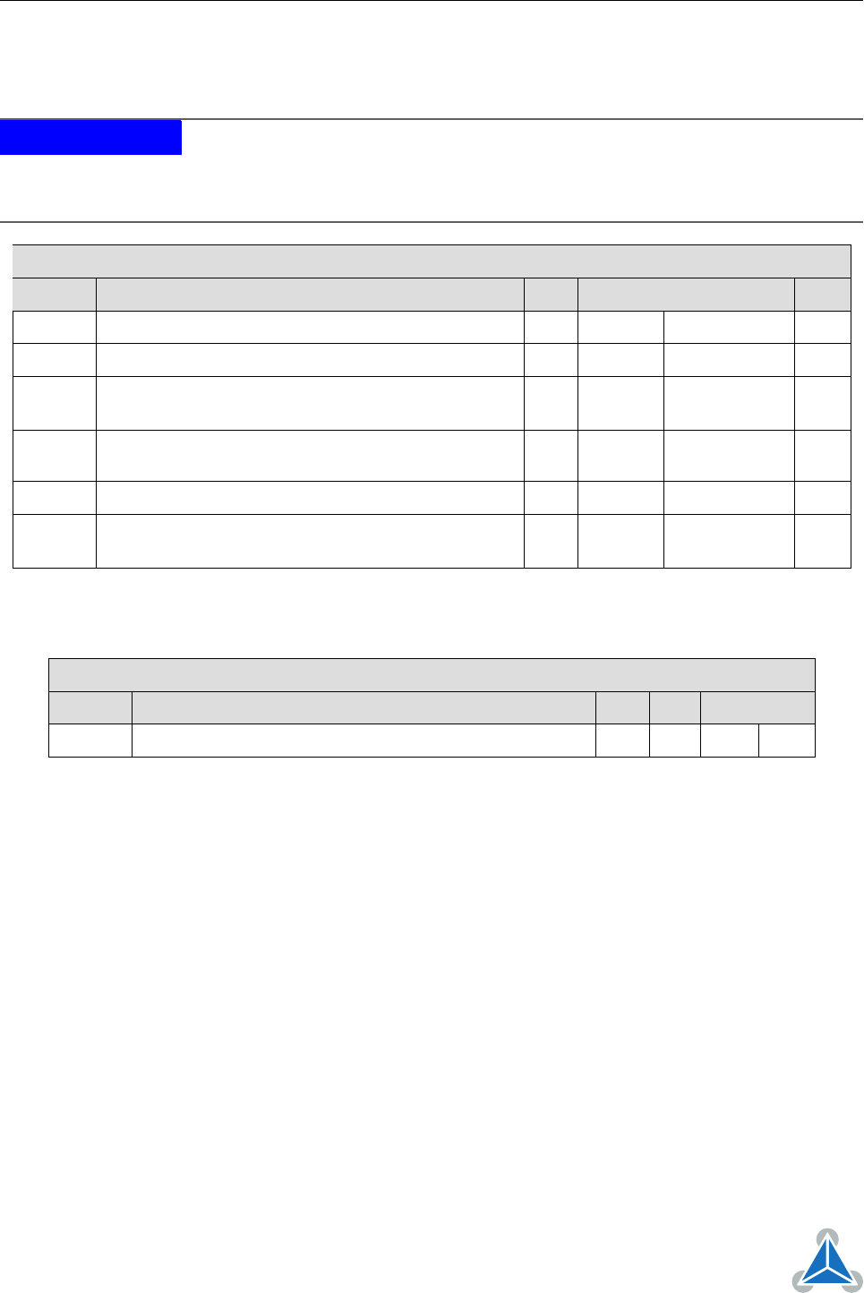
General Operational Ratings
Symbol Parameter Min Typ Max Unit
V
Power
Power supply voltage 10 12. . . 24 30 V
V
USB
Power supply via USB connector 5 V
I
USB
Current withdrawn from USB supply when USB
bus powered (no other supply connected)
70 mA
I
COIL
Motor coil current for sine wave
peak (chopper
regulated, adjustable via software)
0 1500 or 4000 mA
I
MC
Continuous motor current (RMS) 0 1000 or 2800 mA
T
ENV
Environmental temperature at rated current (no
forced cooling reaquired)
-25 60 °C
Table 14: General Operational Ratings of the Module
Operational Ratings of the RS485 Interface
Symbol Parameter Min Typ Max Unit
N
RS485
Number of nodes connected to single RS485 network 256
Table 15: Operational Ratings of the RS485 Interface
©2017 TRINAMIC Motion Control GmbH & Co. KG, Hamburg, Germany
Terms of delivery and rights to technical change reserved.
Download newest version at www.trinamic.com