
User Manual


Table Of Contents
- 1 Features
- 2 Order Codes
- 3 Mechanical and Electrical Interfacing
- 4 Connectors
- 5 Jumper Settings
- 6 LEDs
- 7 Communication
- 8 Functional Description
- 9 Operational Ratings and Characteristics
- 10 Abbreviations used in this Manual
- 11 Figures Index
- 12 Tables Index
- 13 Supplemental Directives
- 14 Revision History
TMCM-1110 Hardware Manual • Hardware Version V2.30 | Document Revision V1.10 • 2017-SEP-06
18 / 26
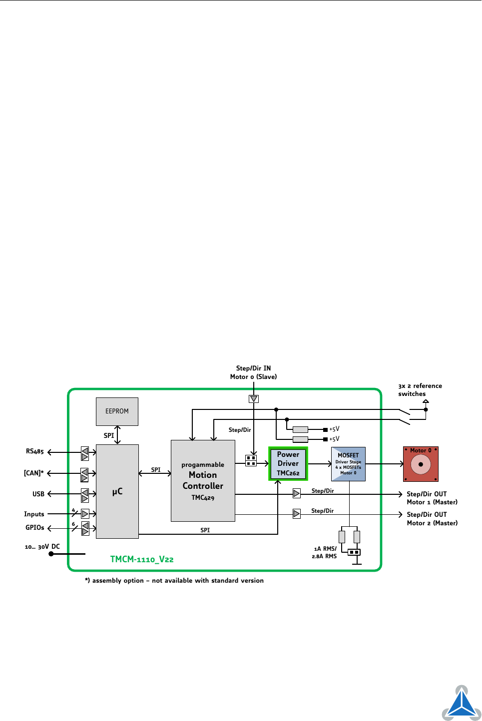
8 Functional Description
The TMCM-1110_V23 is a highly integrated single axis controller/driver module for stepper motors. The
TMCM-1110_V23 can be controlled via RS485 or USB serial interfaces (CAN retro-fit option).
The TMCM-1110_V23 comes with the PC based software development environment TMCL-IDE for the
Trinamic Motion Control Language (TMCL
™
). Using predefined TMCL
™
high level commands like move to
position a rapid and fast development of motion control applications is guaranteed. Whereas the boot
loader is installed during production and testing at TRINAMIC and remains usually untouched throughout
the whole lifetime, the firmware ca be updated by the user.
Communication traffic is kept low since all time critical operations, e.g. ramp calculation, are perfomrmed
on-board. Full remote control of the device with feedback is possible. The firmware of the module can be
updated via any of the serial interfaces.
The TMCM-1110_V23 module contains the following main components:
•
Microcontroller (ARM Cortex-M4
™
, MK20DX128VLK7), responsible for overall control and communica-
tion
•
TMC429 highly integrated 3 axes stepper motor controller. Step-/direction outputs for motor 0
connected to TMC262.
•
TMC262 advanced stepper motor driver IC with stallGuard2
™
and coolStep
™
with MOSFET driver
stage (4x N+P power MOSFETs for bipolar stepper motor) for motor 0
• RS485 and USB transceivers
• On-board voltage regulators (+5V and +3V3) required for supply of all on-board digital circuits
10… 30V DC
µC
EEPROM
USB
4
Inputs
progammable
Motion
Controller
TMC429
3x 2 reference
switches
+5V
6
GPIOs
RS485
+5V
SPI
SPI
SPI
Step/Dir OUT
Motor 1 (Master)
Step/Dir OUT
Motor 2 (Master)
Power
Driver
TMC262
Step/Dir
Step/Dir
MOSFET
Driver Stage
4 x MOSFETs
Motor 0
Step/Dir IN
Motor 0 (Slave)
1A RMS/
2.8A RMS
Motor 0
Step/Dir
*) assembly option – not available with standard version
[CAN]*
TMCM-1110_V22
Figure 8: TMCM-1110 Block Diagram
©2017 TRINAMIC Motion Control GmbH & Co. KG, Hamburg, Germany
Terms of delivery and rights to technical change reserved.
Download newest version at www.trinamic.com