
User Manual


Table Of Contents
- 1 Features
- 2 Order Codes
- 3 Mechanical and Electrical Interfacing
- 4 Connectors
- 5 Jumper Settings
- 6 LEDs
- 7 Communication
- 8 Functional Description
- 9 Operational Ratings and Characteristics
- 10 Abbreviations used in this Manual
- 11 Figures Index
- 12 Tables Index
- 13 Supplemental Directives
- 14 Revision History
TMCM-1110 Hardware Manual • Hardware Version V2.30 | Document Revision V1.10 • 2017-SEP-06
16 / 26
node
n - 1
node
n
Slave Slave
termination
resistor
(120 Ohm)
+5V
GND
pull-up (680R)
pull-down (680R)
RS485- / RS485B
RS485+ / RS485A
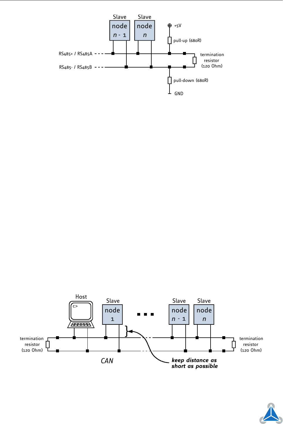
Figure 6: RS485 Bus Lines with Resistor Network
7.2 USB
For remote control and communication with a host system the TMCM-1110_V23 stepRocker provides a USB
2.0 full-speed (12Mbit/s) interface (mini-USB connector). As soon as a USB-Host is connected the module
will accept commands via USB. The TMCM-1110_V23 supports USB self powered operation (External
power supplied via the power supply connector) and USB bus powered operation, also (no external power
is supplied via the power supply connector). During USB bus powered operation, only the core digital
circuit parts will be operational. That is, the microcontroller itself and also the EEPROM. Of course, any
motor movement will not be possible in this mode. This mode has been implemented in order to enable
configuration / parameter setting / read-out, firmware updates etc. by just connecting a USB cable between
the module and a host PC. No other connection / additional power supply is required.
7.3 CAN (Retro-fit Option)
For remote control and communciation with a host system the TMCM-1110_V23 stepRocker can be
equipped with a CAN bus interface. Please note, that it is necessary to add CAN transceiver and filter
capacitor first for the standard TMCM-1110_V23 stepRocker version (see 4.5.1).
For proper operation the following items should be taken into account when setting up a CAN network:
1. BUS STRUCTURE:
The network topology should follow a bus structure as closely as possible. That is, the connection
between each node and the bus itself should be as short as possible. Basically, it should be short
compared to the length of the bus.
c:>
node
1
node
n
- 1
node
n
Host
Slave Slave Slave
CAN
termination
resistor
(120 Ohm)
termination
resistor
(120 Ohm)
}
keep distance as
short as possible
Figure 7: CAN Bus Structure with Termination Resistors
©2017 TRINAMIC Motion Control GmbH & Co. KG, Hamburg, Germany
Terms of delivery and rights to technical change reserved.
Download newest version at www.trinamic.com