
User Manual


Table Of Contents
- 1 Features
- 2 Order Codes
- 3 Mechanical and Electrical Interfacing
- 4 Connectors
- 5 Jumper Settings
- 6 LEDs
- 7 Communication
- 8 Functional Description
- 9 Operational Ratings and Characteristics
- 10 Abbreviations used in this Manual
- 11 Figures Index
- 12 Tables Index
- 13 Supplemental Directives
- 14 Revision History
TMCM-1110 Hardware Manual • Hardware Version V2.30 | Document Revision V1.10 • 2017-SEP-06
15 / 26
7 Communication
7.1 RS485
For remote control and communication with a host system the TMCM-1110_V23 provides a two wire RS485
bus interface. For proper operation the following items should be taken into account when setting up an
RS485 network:
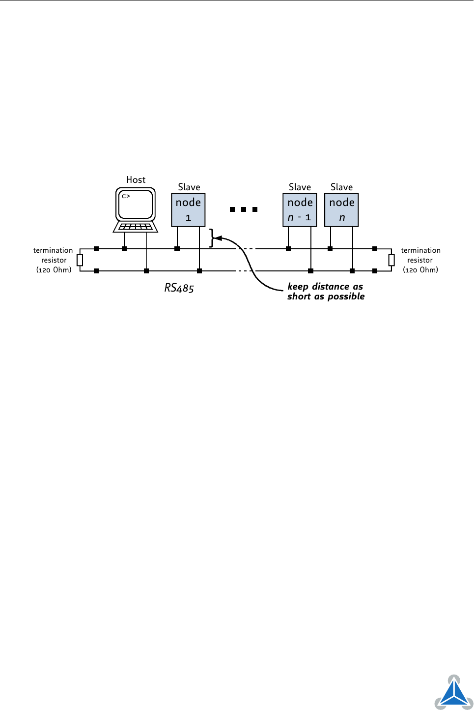
1. BUS STRUCTURE:
The network topology should follow a bus structure as closely as possible. That is, the connection
between each node and the bus itself should be as short as possible. Basically, it should be short
compared to the length of the bus.
c:>
node
1
node
n
- 1
node
n
Host
Slave Slave Slave
RS485
termination
resistor
(120 Ohm)
termination
resistor
(120 Ohm)
}
keep distance as
short as possible
Figure 5: RS485 Bus Structure with Termination Resistors
2. BUS TERMINATION:
Especially for longer busses and/or multiple nodes connected to the bus and/or high communication
speeds, the bus should be properly terminated at both ends. The TMCM-1110_V23 does not intergate
any termination resistor. Therefore, 120 Ohm termination resistors at both ends of the bus have to
be added externally.
3. NUMBER OF NODES:
The RS485 electrical interface stadard (EIA-485) allows up to 32 nodes to be connected to a single
bus. The bus transceiver used on the TMCM-1110_V23 units (SN65HVD3082ED) has just 1/8th of the
standard bus load and allows a maximum of 256 units to be connected to a single RS485 bus.
4. NO FLOATING BUS LINES:
Avoid floating bus lines while neither the host/master nor one of the slaves along the bus line
is transmitting data (all bus nodes switched to receive mode). Floating bus lines may lead to
communication errors. In order to ensure valid signals on the bus it is recommended to use a resistor
network connecting both bus lines to GND resp. +5V. In contrast to the termination resistors this
network is normally required just once per bus. Certain RS485 interface converters available for PCs
already include these additional resistors (e.g. USB-2-485).
©2017 TRINAMIC Motion Control GmbH & Co. KG, Hamburg, Germany
Terms of delivery and rights to technical change reserved.
Download newest version at www.trinamic.com