
User Manual


Table Of Contents
- 1 Features
- 2 Order Codes
- 3 Mechanical and Electrical Interfacing
- 4 Connectors
- 5 Jumper Settings
- 6 LEDs
- 7 Communication
- 8 Functional Description
- 9 Operational Ratings and Characteristics
- 10 Abbreviations used in this Manual
- 11 Figures Index
- 12 Tables Index
- 13 Supplemental Directives
- 14 Revision History
TMCM-1110 Hardware Manual • Hardware Version V2.30 | Document Revision V1.10 • 2017-SEP-06
14 / 26
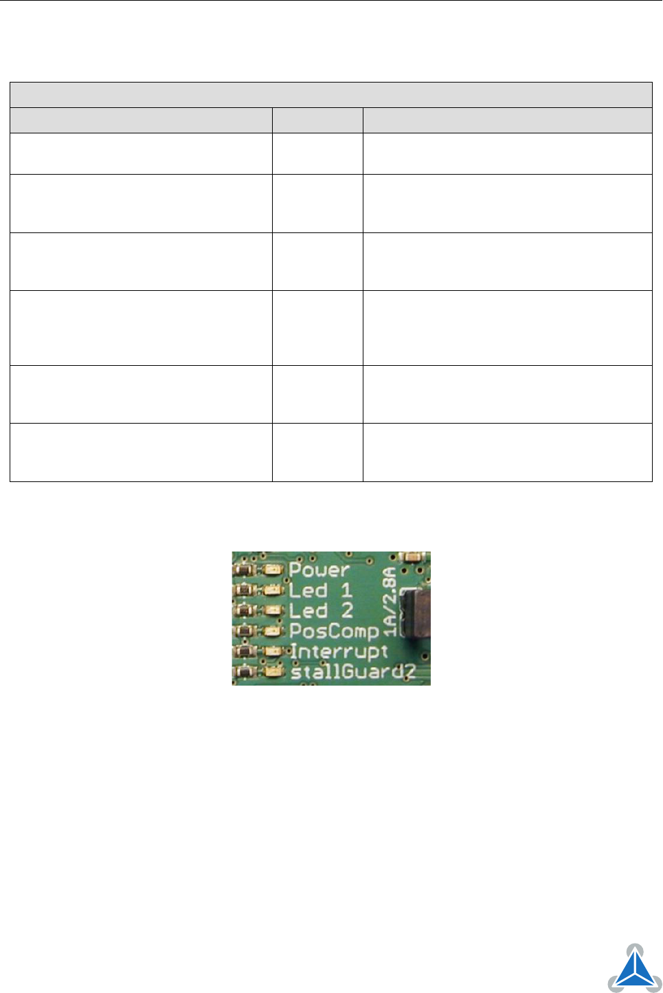
6 LEDs
LED Description
Status Label Description
Power on POWER
This orange LED lights up upon the power
supply is available
LED1 without pre-defined functionality LED1
This yellow LED can be used customer spe-
cific. This LED is connected to PTA5 (pin 31)
of the MK20DX128VLK7 microcontroller.
LED2 without pre-defined functionality LED2
This yellow LED can be used customer spe-
cific. This LED is connected to PTE5 (pin 6)
of the MK20DX128VLK7 microcontroller.
POSCOMP output used POSCOMP
This yellow LED lights up if the POSCOMP
output of the TMC429 is used. POSCOMP is
available for triggering when moving over a
programmable position.
Interrupt detected Interrupt
This orange LED lights up upon interrupts.
The LED is connected to the nIND_SDO_C
pin of the TMC429.
stallGuard2™ detected stallGuard2
This red LED lights up upon stalling condi-
tions. The LED is connected to the SG_TST
pin of the TMC262.
Table 13: LED Description
Figure 4: TMCM-1110 LEDs
©2017 TRINAMIC Motion Control GmbH & Co. KG, Hamburg, Germany
Terms of delivery and rights to technical change reserved.
Download newest version at www.trinamic.com