
User Manual


Table Of Contents
- 1 Features
- 2 Order Codes
- 3 Mechanical and Electrical Interfacing
- 4 Connectors
- 5 Jumper Settings
- 6 LEDs
- 7 Communication
- 8 Functional Description
- 9 Operational Ratings and Characteristics
- 10 Abbreviations used in this Manual
- 11 Figures Index
- 12 Tables Index
- 13 Supplemental Directives
- 14 Revision History
TMCM-1110 Hardware Manual • Hardware Version V2.30 | Document Revision V1.10 • 2017-SEP-06
12 / 26
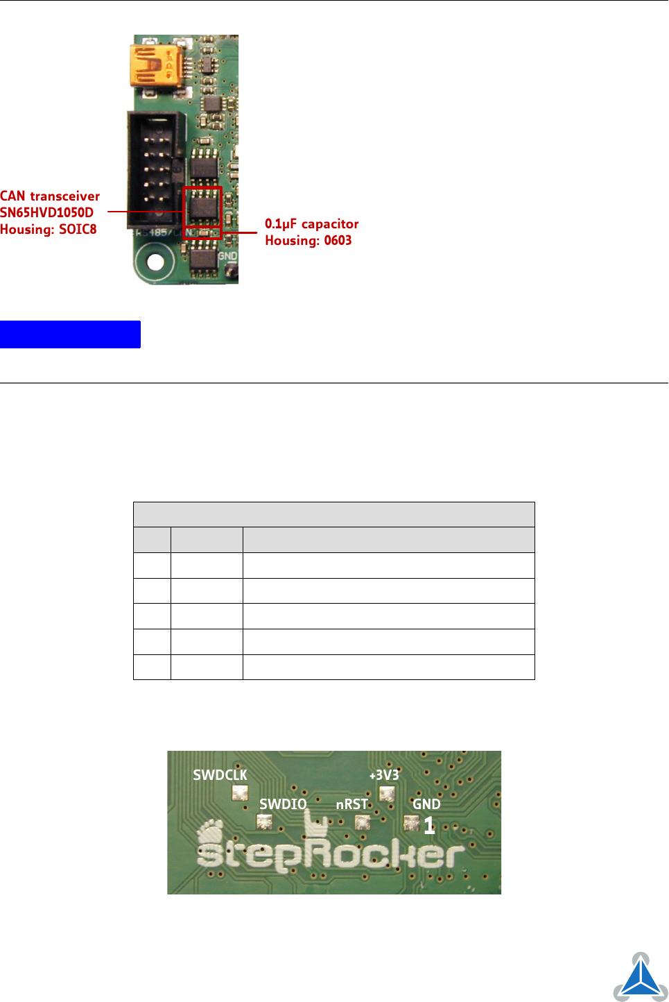
CAN transceiver
SN65HVD1050D
Housing: SOIC8
0.1µF capacitor
Housing: 0603
The table above shows the pin configuration
for CAN, too. Before starting with CAN it
is necessary to solder a SN65HVD1050D
CAN transceiver with housing SOIC8 and a
0.1
µ
capacitor with housing 0603 on the
TMCM-1110_V23 stepRocker. Afterwards,
the stepRocker is ready for using the CAN
interface.
Because of the pin assignment CAN and
RS485 can be used at the same time.
Please note: it is not necessary to remove
the RS485 transceiver.
NOTICE
Note
For setting the
step pulse length
global parameter
86
is used. Adjust this
parameter with the
SGP
command. Refer to the TMCL Firmware Manual of the
stepRocker for further information.
4.9 Microcontroller Programming Interface
The programming pads for the microcontroller are located on the bottom side of the module. They are
connected directly to the related processor pins - resp. GND or on-board generated +3V3 supply. These
pins are used for programming of the bootloader and firmware during production + testing of the module.
Programming Pads
Pin Label Description
1 GND Module and signal ground
2 +3V3 +3V3 DC supply - generated on-board
3 nRST Hardware reset input
4 SWDIO Serial wire data I/O
5 SWDCLK Serial wire clock
Table 11: Programming Pads on Bottom of the PCB
SWDCLK
nRST
+3V3
GND
1
SWDIO
©2017 TRINAMIC Motion Control GmbH & Co. KG, Hamburg, Germany
Terms of delivery and rights to technical change reserved.
Download newest version at www.trinamic.com