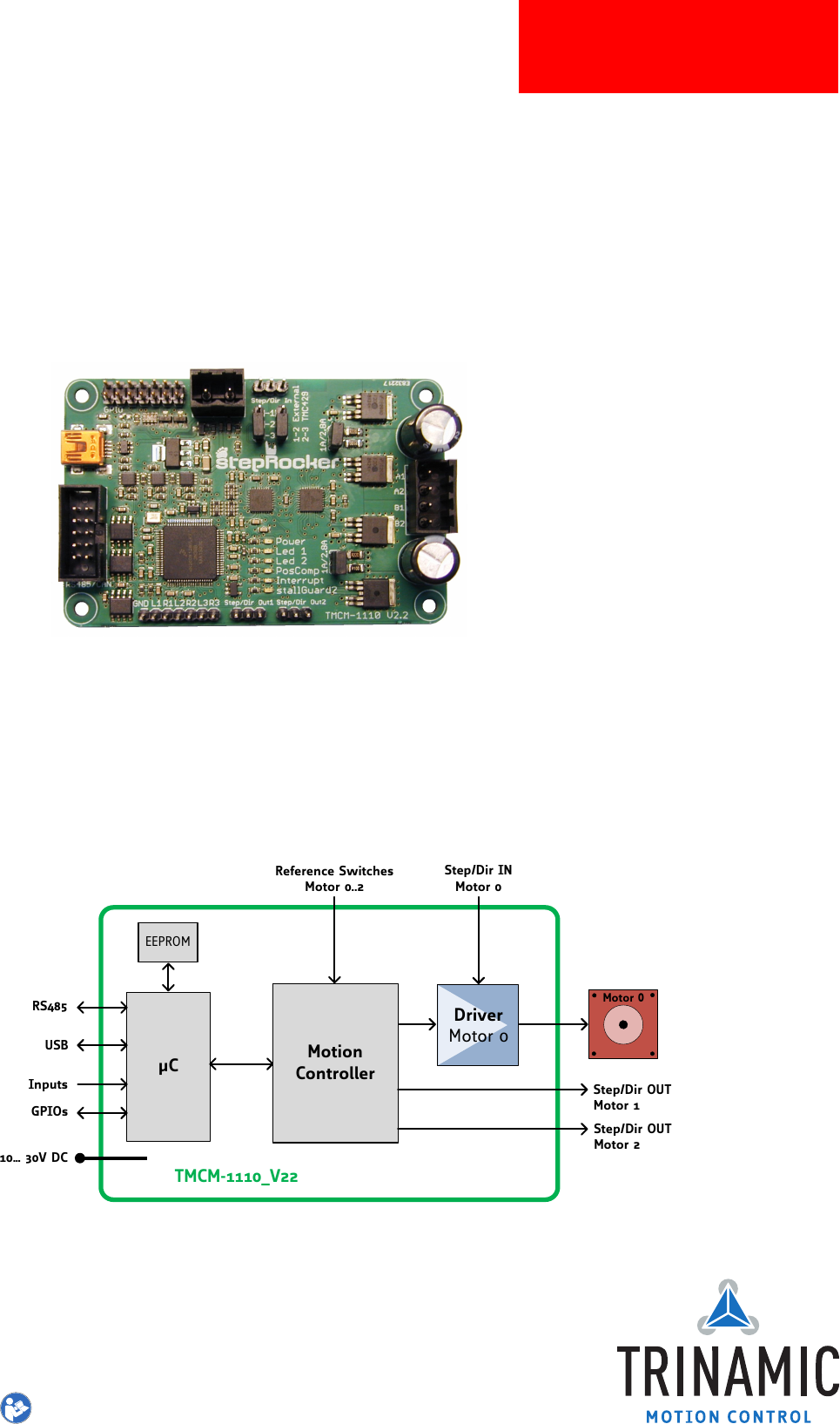
MODULE Module for Stepper Motors TMCM-1110 Hardware Manual Hardware Version V2.30 | Document Revision V1.10 • 2017-SEP-06 The TMCM-1110_V23 stepRocker is a single axis motor controller/driver board for 2-phase bipolar stepper motors. It features the TRINAMIC controller/driver chain consisting of TMC429 and TMC262 in combination with an ARM Cortex-M4™ (MK20DX128VLK7) processor. The Module is intended to be a fully functional development platform.
/ 26 TMCM-1110 Hardware Manual • Hardware Version V2.30 | Document Revision V1.10 • 2017-SEP-06 Contents 1 Features 3 2 Order Codes 4 3 Mechanical and Electrical Interfacing 3.1 Size of board . . . . . . . . . . . . . . . . . . . . . . . . . . . . . . . . . . . . . . . . . . . . . . . . 5 5 4 Connectors 4.1 Power Connector . . . . . . . . . . . . . . . . . . . . . . . 4.2 I/O Connector (Microcontroller) . . . . . . . . . . . . . . . 4.3 Motor Connector . . . . . . . . . . . . . . . . . . . . . . .
TMCM-1110 Hardware Manual • Hardware Version V2.30 | Document Revision V1.10 • 2017-SEP-06 1 3 / 26 Features The TMCM-1110_V23 stepRocker is a single axis motor controller/driver board for 2-phase bipolar stepper motors. It features the TRINAMIC controller/driver chain consisting of TMC429 and TMC262 in combination with an ARM Cortex-M4™ (MK20DX128VLK7) processor. The Module is intended to be a fully functional development platform.
TMCM-1110 Hardware Manual • Hardware Version V2.30 | Document Revision V1.10 • 2017-SEP-06 2 4 / 26 Order Codes The standard version of the stepRocker has RS485 and USB interfaces (CAN transceiver not assembled). The module is pre-programmed with TRINAMICs TMCL™ firmware with all available features.
/ 26 TMCM-1110 Hardware Manual • Hardware Version V2.30 | Document Revision V1.10 • 2017-SEP-06 3 3.1 Mechanical and Electrical Interfacing Size of board The board with the controller/driver electronics has an overall size of 85mm x 55mm x 15mm without mating connectors. It offers four mounting holes for M3 screws (3.2mm diameter). All four mounting holes are connected to the ground plane (signal and supply ground) of the module. 4 4 Ø 3.
/ 26 TMCM-1110 Hardware Manual • Hardware Version V2.30 | Document Revision V1.10 • 2017-SEP-06 4 Connectors The TMCM-1110_V23 stepRocker has nine connectors altogehter. There are two screw connectors for power and motor and two interface connectors (mini-USB and RS485).
TMCM-1110 Hardware Manual • Hardware Version V2.30 | Document Revision V1.10 • 2017-SEP-06 7 / 26 Connector Connector type on-board Mating connector type Ref. switches Multi-pin-connector, 7pin, 2.54mm pitch Female connector with 2.54mm pitch Driver In Multi-pin-connector, 3 pin, 2.54mm pitch Female connector with 2.54mm pitch Controller Out 1, 2 Multi-pin-connector, 3 pin, 2.54mm pitch Female connector with 2.
TMCM-1110 Hardware Manual • Hardware Version V2.30 | Document Revision V1.10 • 2017-SEP-06 4.1 8 / 26 Power Connector Power Supply Connector Pin Assigment Pin Label Direction Description 1 GND Power (GND) Common system supply and signal ground 2 10. . .
TMCM-1110 Hardware Manual • Hardware Version V2.30 | Document Revision V1.10 • 2017-SEP-06 Pin Label Direction 9 AIN_0 in Analog input (can be used as home switch). Input voltage range: 0. . . +10V Resolution: 12bit (0. . . 4095) 10 PHASE_A in Encoder input channel A (+5V compatible, internal pull-up to +5V) 11 OpenDrain_1 out 12 PHASE_B in 13 OpenDrain_2 out 14 PHASE_Z in 9 / 26 Description Open-drain output (max.
TMCM-1110 Hardware Manual • Hardware Version V2.30 | Document Revision V1.
TMCM-1110 Hardware Manual • Hardware Version V2.30 | Document Revision V1.10 • 2017-SEP-06 Pin Label Direction Description 3 D+ bi-directional USB Data+ 4 ID 5 GND 11 / 26 Connected to signal and system ground Power (GND) Signal and system ground Table 8: USB Connector Pin Assignment 4.7 Step/Dir Input Connector (Motor 0) The TMCM-1110 stepRocker is equipped with a step/dir input connector for motor 0.
TMCM-1110 Hardware Manual • Hardware Version V2.30 | Document Revision V1.10 • 2017-SEP-06 12 / 26 The table above shows the pin configuration for CAN, too. Before starting with CAN it is necessary to solder a SN65HVD1050D CAN transceiver with housing SOIC8 and a 0.1µ capacitor with housing 0603 on the TMCM-1110_V23 stepRocker. Afterwards, the stepRocker is ready for using the CAN interface. Because of the pin assignment CAN and RS485 can be used at the same time.
TMCM-1110 Hardware Manual • Hardware Version V2.30 | Document Revision V1.10 • 2017-SEP-06 5 13 / 26 Jumper Settings The TMCM-1110_V23 stepRocker offers a number of jumpers for selection of different settings in hardware. Select motion controller Select motor current Select motor current Figure 3: Jumper Settings of the TMCM-1110_V23 stepRocker Jumpers of the TMCM-1110_V23 stepRocker Jumper Label Select motor current 1A/2.8A Jumper plugged: motor current up to 2.
TMCM-1110 Hardware Manual • Hardware Version V2.30 | Document Revision V1.10 • 2017-SEP-06 6 14 / 26 LEDs LED Description Status Label Description Power on POWER This orange LED lights up upon the power supply is available LED1 without pre-defined functionality LED1 This yellow LED can be used customer specific. This LED is connected to PTA5 (pin 31) of the MK20DX128VLK7 microcontroller. LED2 without pre-defined functionality LED2 This yellow LED can be used customer specific.
/ 26 TMCM-1110 Hardware Manual • Hardware Version V2.30 | Document Revision V1.10 • 2017-SEP-06 7 Communication 7.1 RS485 For remote control and communication with a host system the TMCM-1110_V23 provides a two wire RS485 bus interface. For proper operation the following items should be taken into account when setting up an RS485 network: 1. BUS STRUCTURE: The network topology should follow a bus structure as closely as possible.
/ 26 TMCM-1110 Hardware Manual • Hardware Version V2.30 | Document Revision V1.10 • 2017-SEP-06 Slave Slave node n- 1 node n +5V pull-up (680R) RS485+ / RS485A termination resistor (120 Ohm) RS485- / RS485B pull-down (680R) GND Figure 6: RS485 Bus Lines with Resistor Network 7.2 USB For remote control and communication with a host system the TMCM-1110_V23 stepRocker provides a USB 2.0 full-speed (12Mbit/s) interface (mini-USB connector).
TMCM-1110 Hardware Manual • Hardware Version V2.30 | Document Revision V1.10 • 2017-SEP-06 17 / 26 2. BUS TERMINATION: Especially for longer busses and/or multiple nodes connected to the bus and/or high communication speeds, the bus should be properly terminated at both ends. The TMCM-1110_V23 does not integrate any termination resistor. Therefore, 120 Ohm termination resistors at both ends of the bus have to be added externally. ©2017 TRINAMIC Motion Control GmbH & Co.
/ 26 TMCM-1110 Hardware Manual • Hardware Version V2.30 | Document Revision V1.10 • 2017-SEP-06 8 Functional Description The TMCM-1110_V23 is a highly integrated single axis controller/driver module for stepper motors. The TMCM-1110_V23 can be controlled via RS485 or USB serial interfaces (CAN retro-fit option). The TMCM-1110_V23 comes with the PC based software development environment TMCL-IDE for the Trinamic Motion Control Language (TMCL™).
TMCM-1110 Hardware Manual • Hardware Version V2.30 | Document Revision V1.10 • 2017-SEP-06 8.1 19 / 26 Extensions of the TMCM-1110 stepRocker The TMCM-1110_V23 stepRocker can be extended for multi-axes systems with up-to 3 axes. The stepRocker itself can be configured as master or slave. An example for a three axes system is shown below. The stepRocker at the top is configured as master while the other two are configured as slave.
/ 26 TMCM-1110 Hardware Manual • Hardware Version V2.30 | Document Revision V1.10 • 2017-SEP-06 9 Operational Ratings and Characteristics NOTICE Never Exceed the absolute maximum ratings! Keep the power supply voltage below the upper limit of +30V! Otherwise the board electronics will seriously be damaged! Especially, when the selected operating voltage is near the upper limit a regulated power supply is highly recommended.
TMCM-1110 Hardware Manual • Hardware Version V2.30 | Document Revision V1.10 • 2017-SEP-06 10 Abbreviations used in this Manual Abbreviation Description IDE Integrated Development Environment LED Light Emmitting Diode RMS Root Mean Square value TMCL TRINAMIC Motion Control Language Table 16: Abbreviations used in this Manual ©2017 TRINAMIC Motion Control GmbH & Co. KG, Hamburg, Germany Terms of delivery and rights to technical change reserved. Download newest version at www.trinamic.
TMCM-1110 Hardware Manual • Hardware Version V2.30 | Document Revision V1.10 • 2017-SEP-06 11 1 2 3 4 5 22 / 26 Figures Index Board Dimensions and Positions of Mounting Holes (all Values in mm) . . TMCM-1110 stepRocker Connectors . Jumper Settings of the TMCM1110_V23 stepRocker . . . . . . . . . . TMCM-1110 LEDs . . . . . . . . . . . . RS485 Bus Structure with Termination Resistors . . . . . . . . . . . . . . . . . 5 6 13 14 15 ©2017 TRINAMIC Motion Control GmbH & Co.
TMCM-1110 Hardware Manual • Hardware Version V2.30 | Document Revision V1.10 • 2017-SEP-06 12 1 2 3 4 5 6 7 8 9 10 23 / 26 Tables Index TMCM-1110_V23 Order Code . . . . . Connector Types and Mating Connectors of the TMCM-1110 stepRocker . . Power Supply Connector Pin Assignment I/O Connector Pin Assignment . . . . Motor Connector Pin Assignment . . Reference Switch Connector Pin Assignment . . . . . . . . . . . . . . . . . RS485/CAN Connector Pin Assignment USB Connector Pin Assignment . . . .
TMCM-1110 Hardware Manual • Hardware Version V2.30 | Document Revision V1.10 • 2017-SEP-06 13 24 / 26 Supplemental Directives 13.1 Producer Information 13.2 Copyright TRINAMIC owns the content of this user manual in its entirety, including but not limited to pictures, logos, trademarks, and resources. © Copyright 2017 TRINAMIC. All rights reserved. Electronically published by TRINAMIC, Germany.
TMCM-1110 Hardware Manual • Hardware Version V2.30 | Document Revision V1.10 • 2017-SEP-06 25 / 26 or of any other nature are made hereunder with respect to information/specification or the products to which information refers and no guarantee with respect to compliance to the intended use is given. In particular, this also applies to the stated possible applications or areas of applications of the product.
TMCM-1110 Hardware Manual • Hardware Version V2.30 | Document Revision V1.10 • 2017-SEP-06 14 14.1 26 / 26 Revision History Hardware Revision Version Date Author Description V1.3 2013-NOV-26 GE Series version with Samsung Cortex-M0 processor V2.2 2016-SEP-26 GE Processor changed to Cortex-M4 microcontroller V2.3 2017-AUG-02 GE Minor changes: silksreen corrected, plating added to mounting holes and resistor values of input divider adapted in order to improve compatibility with version V1.