MODULE Module for Stepper TMCM-1076 Hardware Manual Hardware Version V1.10 | Document Revision V1.00 • 2018-JUN-25 The TMCM-1076 is an easy to use stepper motor driver module. The module is controlled via a step and direction interface. One configuration pin selects the current control mode between stealthChop™ for absolute silent motor control and spreadCycle™ for high speed. A TTL UART interface allows for more advanced configuration and permanent parameter storage via TMCL™IDE.
/ 22 TMCM-1076 Hardware Manual • Hardware Version V1.10 | Document Revision V1.00 • 2018-JUN-25 Contents 1 Features 1.1 General Features . . . . . . . 1.2 TRINAMIC’s Unique Features 1.2.1 stealthChop™ . . . . . 1.2.2 spreadCycle™ . . . . . 1.3 stallGuard2 . . . . . . . . . . . 1.4 coolStep . . . . . . . . . . . . . . . . . . . . . . . . . . . . . . . . . . . . . . . . . . . . . . . . . . . . . . . . . . . . . . . . . . . . . . . . . . . . . . . . . . . . . . . . . . . . . . . . . . . . .
TMCM-1076 Hardware Manual • Hardware Version V1.10 | Document Revision V1.00 • 2018-JUN-25 1 3 / 22 Features The TMCM-1076 is an easy to use stepper driver unit with state of the art feature set. It is highly integrated and offers a convenient handling. TMCM-1076 can be used with a simple step and direction interface and can be configured using a TTL UART interface. stallGuard2 and coolStep can be configured via TTL UART interface and are disabled by default. 1.
TMCM-1076 Hardware Manual • Hardware Version V1.10 | Document Revision V1.00 • 2018-JUN-25 1.2 1.2.1 4 / 22 TRINAMIC’s Unique Features stealthChop™ stealthChop is an extremely quiet mode of operation for low and medium velocities. It is based on a voltage mode PWM. During standstill and at low velocities, the motor is absolutely noiseless. Thus, stealthChop operated stepper motor applications are very suitable for indoor or home use. The motor operates absolutely free of vibration at low velocities.
TMCM-1076 Hardware Manual • Hardware Version V1.10 | Document Revision V1.00 • 2018-JUN-25 1.3 5 / 22 stallGuard2 stallGuard2 is a high-precision sensorless load measurement using the back EMF of the motor coils. It can be used for stall detection as well as other uses at loads below those which stall the motor. The stallGuard2 measurement value changes linearly over a wide range of load, velocity, and current settings. At maximum motor load, the value reaches zero or is near zero.
TMCM-1076 Hardware Manual • Hardware Version V1.10 | Document Revision V1.00 • 2018-JUN-25 2 6 / 22 Order Codes Order Code Description Size (LxWxH) TMCM-1076 Controller/Driver Module without motor, +24V DC, 3A RMS, TTL UART interface (9600bps default), S/D interface, Enable, Mode Select 60mm x 60mm x 13mm Table 1: Order codes modules Order Code Description TMCM-1076-CABLE Cable loom for TMCM-1076.
TMCM-1076 Hardware Manual • Hardware Version V1.10 | Document Revision V1.00 • 2018-JUN-25 3 3.1 7 / 22 Mechanical and Electrical Interfacing TMCM-1076 Dimensions and Weight The dimensions of the TMCM-1076 are approximately 60mm x 60mm x 13mm. There are four mounting holes for M3 screws for mounting the TMCM-1076. These mounting holes are located in the bottom / base plate and accessible after removing the top cover (see 5, right figure, mounting holes marked red).
TMCM-1076 Hardware Manual • Hardware Version V1.10 | Document Revision V1.00 • 2018-JUN-25 4 8 / 22 Connectors and LEDs Power + I/O 1 9 4 LED 1 Motor Figure 6: TMCM-1076 connectors 4.1 Motor Connector Pin no.
TMCM-1076 Hardware Manual • Hardware Version V1.10 | Document Revision V1.00 • 2018-JUN-25 4.2 9 / 22 Power + I/O Connector Pin no.
TMCM-1076 Hardware Manual • Hardware Version V1.10 | Document Revision V1.00 • 2018-JUN-25 4.3 10 / 22 TTL UART Connection To connect via the TTL UART interface to a host PC, we suggest using a USB serial converter from TTL-UART (5V) to USB interface. Communication with the host PC, for example when using TRINAMIC’s TMCL-IDE, is done via the Virtual COM port installed by the converter driver. More information on the TMCL-IDE and the latest release can be found here: www.trinamic.
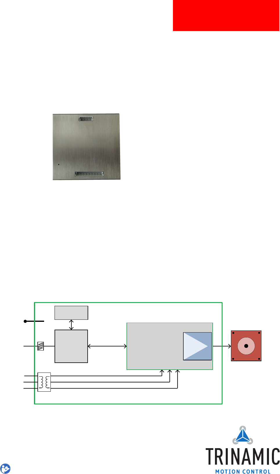
/ 22 TMCM-1076 Hardware Manual • Hardware Version V1.10 | Document Revision V1.00 • 2018-JUN-25 5 Functional Description 5.1 Typical Application Wiring Wire the TMCM-1076 as shown in the following figures. • Connect the the power supply to V+ and GND. • Connect the Step and Direction signals to your motion controller. • At power up time, the EN input must be low (= driver stage disabled)! • Optional: Connect UART to a TTL UART interface with 5V logic levels.
/ 22 TMCM-1076 Hardware Manual • Hardware Version V1.10 | Document Revision V1.00 • 2018-JUN-25 5.2 Optically Isolated Inputs with Common Anode Input The control inputs of the TMCM-1076 are optically isolated (not the TTL UART interface). All optocouplers share one common anode (COMM) input as shown in the figure above. TMCM-1076 / PD-x-1076 3.
/ 22 TMCM-1076 Hardware Manual • Hardware Version V1.10 | Document Revision V1.00 • 2018-JUN-25 TMCM-1076 / PD-x-1076 +5V >5V to +24V COMM Rexternal 270 Ω A1 STEP A2 GND Rexternal B1 270 Ω Driver & Controller DIR GND Rexternal 270 Ω GND Rexternal 270 Ω B2 M EN CHOP GND GND Figure 9: Inputs with common anode input with >5V to 24V The series resistors in the TMCM-1076 are 270mOhms.
TMCM-1076 Hardware Manual • Hardware Version V1.10 | Document Revision V1.00 • 2018-JUN-25 5.4 14 / 22 Thermal Behavior The motor current may be set to the specified maximum current of 3A RMS / 4.2A peak for the TMCM1076 which is slightly above the maximum specified current for the stepper motor options (available as PD57/PD60-x-1076). Typically, at this nominal current setting the stepper motor and the driver electronics will get hot.
/ 22 TMCM-1076 Hardware Manual • Hardware Version V1.10 | Document Revision V1.00 • 2018-JUN-25 6 6.1 Operational Ratings and Characteristics Absolute Maximum Ratings Parameter Min Max Unit Supply voltage +10 +30 V Working temperature -30 +40 °C Motor coil current / sine wave peak 4.2 A Continuous motor current (RMS) 3 A NOTICE Never Exceed the absolute maximum ratings! Stresses above those listed under "‘Absolute Maximum Ratings"’ may cause permanent damage to the device.
/ 22 TMCM-1076 Hardware Manual • Hardware Version V1.10 | Document Revision V1.00 • 2018-JUN-25 TTL UART high level voltage VT T L H TTL UART output voltage VT T L_OU T 3.25 5 5 V V Table 10: Operational ratings of optically isolated inputs and TTL UART interface 6.
TMCM-1076 Hardware Manual • Hardware Version V1.10 | Document Revision V1.
TMCM-1076 Hardware Manual • Hardware Version V1.10 | Document Revision V1.00 • 2018-JUN-25 8 18 / 22 Figures Index 1 2 3 4 5 Motor coil sine wave current using stealthChop (measured with current probe) . . . . . . . . . . . . . . . . . . . 4 spreadCycle principle . . . . . . . . . . 4 stallGuard2 Load Measurement as a Function of Load . . . . . . . . . . . . 5 Energy Efficiency Example with coolStep 5 TMCM-1076 top view mechanical dimensions (left) and position of mounting holes (marked red / right).
TMCM-1076 Hardware Manual • Hardware Version V1.10 | Document Revision V1.00 • 2018-JUN-25 9 19 / 22 Tables Index 1 2 3 4 5 6 7 9 Order codes modules . . . . . . . . Order codes cable loom . . . . . . . TMCM-1076 dimensions and weight Motor connector pinning . . . . . . Power + I/O connector pinning . . . LED state description . . . . . . . . . Additional resistor reference values Electrical Characteristics . . . . . . . . . . . . . . . 6 6 7 8 9 10 13 15 ©2018 TRINAMIC Motion Control GmbH & Co.
TMCM-1076 Hardware Manual • Hardware Version V1.10 | Document Revision V1.00 • 2018-JUN-25 10 20 / 22 Supplemental Directives 10.1 Producer Information 10.2 Copyright TRINAMIC owns the content of this user manual in its entirety, including but not limited to pictures, logos, trademarks, and resources. © Copyright 2018 TRINAMIC. All rights reserved. Electronically published by TRINAMIC, Germany.
TMCM-1076 Hardware Manual • Hardware Version V1.10 | Document Revision V1.00 • 2018-JUN-25 21 / 22 or of any other nature are made hereunder with respect to information/specification or the products to which information refers and no guarantee with respect to compliance to the intended use is given. In particular, this also applies to the stated possible applications or areas of applications of the product.
TMCM-1076 Hardware Manual • Hardware Version V1.10 | Document Revision V1.00 • 2018-JUN-25 11 11.1 22 / 22 Revision History Hardware Revision Version Date Author Description 1.00 2018-FEB-28 GE First prototype version. 1.10 2018-APR-09 GE Pull-ups for opto-isolator changed to lower values (to be compatible with TMCM-1070). Table 14: Hardware Revision 11.2 Document Revision Version Date Author Description 1.00 2018-JUN-25 GE First release.