
User manual

TMC603-EVAL MANUAL (V. 1.01 / April 14th, 2009) 7
Copyright © 2009 TRINAMIC Motion Control GmbH & Co. KG
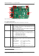
3. Connect the evaluation board via null-modem cable with a RS232 port of the PC
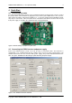
4. Start the PC software EVAL603HallFX.EXE
5. Select the COM port (COM1, COM2, …) and push “Open”
6. Select the mode of operation (Block, HallFX, Closed Loop, …) under “Configuration Options”
a. For operating mode “Block, HallFX, Open Loop” you need the following parameters
“Resistance [Ohm]” of the motor coils
“Maximum Current [A]” of the motor
“BEMF constant [rpm/V]” of the motor
Number of “Pole pairs”
“Speed [rpm]” is the starting point of ramp up
“Acceleration [rpm/s]” for startup
“Ramp up time [ms]” for startup
“Wait start pos. [ms]” is the time to turn to the definite start position
“Direction” of the rotation (CCW, CW)
“Speed Ref. [rpm]” is the reference to change the motor speed
“Speed Ctl. Time [ms]” is the time to count up or down the PWM duty cycle
“Duty cycle ref. [%]” if speed control is disabled (optional)
b. For operating mode “Block, HallFX, Closed Loop” you need the following parameters
“Maximum Current [A]” of the motor
Number of “Pole pairs”
“Speed [rpm]” is the end point of ramp up
“Acceleration [rpm/s]” for start up
“Direction” of the rotation (CCW, CW)
“Current Ref. [A]” is the current value for startup
“Current Time [ms]” is the regulation time of the current controller
“Current Control Kp” is the proportional gain of the controller
“Speed Ref. [rpm]” is the reference to change the motor speed
“Speed Ctl. Time [ms]” is the time to count up or down the PWM duty cycle
“Duty cycle ref. [%]” if speed control is disabled (optional)
c. For operating mode “Block, Hall Sensor” you need the following parameters
“Chopper” mode selection (Low side, High side, Dual chopper)
“Invert Hall Sensors” (optional)
“Maximum Current [A]” of the motor
Number of “Pole pairs”
“Direction” of the rotation (CCW, CW)
“Speed Ref. [rpm]” is the reference to change the motor speed
“Speed Ctl. Time [ms]” is the time to count up or down the PWM duty cycle
“Duty cycle ref. [%]” if speed control is disabled (optional)
d. For operating mode “Sine, HallFX, Closed Loop”
Set the same parameters like operating mode “Block, HallFX, Closed Loop”
Initialization of sine startup via operating mode “Block, HallFX, Closed Loop”
(pls. refer chapter 6.4.4, page 18)
7. Start the motor by pushing the button “Start” under “Motor Control”
8. Change the motor speed
a. Enter the new speed reference value under “Speed Ref. [rpm]”
b. Push the button “Set”
9. Change the PWM duty cycle
a. Enter the new PWM duty cycle reference value under “Duty cycle ref. [%]”
b. Disable the option “Enable speed control”
c. Push the button “Set”
10. Stop the motor by pushing the button “Stop” under “Motor Control”