
User manual

TMC603-EVAL MANUAL (V. 1.01 / April 14th, 2009) 13
Copyright © 2009 TRINAMIC Motion Control GmbH & Co. KG
Option
Function
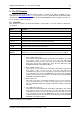
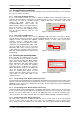
Chopper
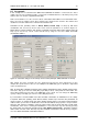
Here you can select the chopper mode. This option is available in “Block, Hall
Sensor” mode only. The chopper frequency is 20kHz.
1. Low side chopper mode
In this chopper mode the low side drivers are chopped only.
2. High side chopper mode
In this chopper mode the high side drivers are chopped only.
3. Dual chopper mode
Both, the high side drivers and the low side drivers are chopped with the
same signal. The dual chopper mode is required for HallFX.
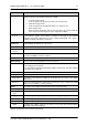
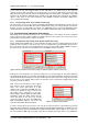
Invert Hall
Sensors
This option can be selected optionally if the signals of the hall sensors are inverted
to the hallFX™ signals. If this option is unused the firmware of the TMC603
evaluation board will configured the correct setting automatically. This option is
available in “Block, Hall Sensor” mode only.
Motor
Parameters
In these input boxes you can enter the required motor parameters. You can find the
required data in the datasheet of the motor.
Resistance
This parameter is the resistance of the motor coils.
Maximum
current
This parameter is the peak current of the motor.
BEMF const.
This parameter is the BEMF constant of the motor. Please take into account that
the unit of the BEMF constant is in rpm/V
Pole pairs
This is the number of pole pairs of the motor.
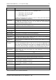
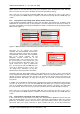
Motor Startup
Here you can enter the parameters for motor start up.
Speed
If you selected the operating mode “Block, HallFX, Open Loop”, the value “Speed”
is the starting point of ramp up.
If you selected the operating mode “Block, HallFX, Closed Loop”, the value “Speed”
is the end point of ramp up.
Acceleration
This value is the angle acceleration for startup.
Ramp up time
The ramp up time is the time duration of startup.
Wait start pos.
This value is the time before ramp up. In this time the rotor turns to the definite
start position.
Direction
This is the rotating direction of the motor. The direction can be changed by setting
CCW (counter clockwise) or CW (clockwise).
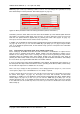
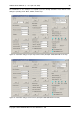
Status
This option shows display fields with actual values and status flags.
Motor speed
The field “Motor speed “displays the actual speed of the motor.
PWM duty
cycle
The field “PWM duty cycle” displays the actual PWM duty cycle.
Supply voltage
The filed “Supply voltage” displays the actual power supply voltage.
Off
The status flag “Off” lights up if the motor is stopped.
On
The status flag “On” lights up if the motor is started.
HallFX
The status flag “HallFX” lights up if the motor is run by using the sensorless BLDC
back EMF commutation hallFX™
Table 5: Several parts of PC software (continued)