TMC603EVAL – MANUAL Evaluation board for the TMC603 three phase motor driver with BLDC back EMF commutation hallFX™ ® TRINAMIC Motion Control GmbH & Co. KG Sternstraße 67 D – 20357 Hamburg GERMANY www.trinamic.com 1 Features The TMC603 evaluation board makes it possible to evaluate the features of the TMC603 three phase BLDC motor driver with back EMF commutation hallFX™. On the evaluation board the Infineon XC886 microcontroller is used to control the TMC603.
TMC603-EVAL MANUAL (V. 1.01 / April 14th, 2009) Life support policy TRINAMIC Motion Control GmbH & Co. KG does not authorize or warrant any of its products for use in life support systems, without the specific written consent of TRINAMIC Motion Control GmbH & Co. KG. Life support systems are equipment intended to support or sustain life, and whose failure to perform, when properly used in accordance with instructions provided, can be reasonably expected to result in personal injury or death.
TMC603-EVAL MANUAL (V. 1.01 / April 14th, 2009) 3 2 Contents 1 FEATURES .......................................................................................................................................... 1 2 CONTENTS ......................................................................................................................................... 3 3 GENERAL DESCRIPTION ....................................................................................................................
TMC603-EVAL MANUAL (V. 1.
TMC603-EVAL MANUAL (V. 1.01 / April 14th, 2009) 5 4 Quick Start 4.1 Connecting the motor For a first quick start, plug the jumpers on the evaluation board like shown in Figure 2. Please check if the jumpers X212, X213 and X214 are plugged. Connect a three phase BLDC motor to the connector X301 (motor coil output). The pins are marked by “U”, “V” and “W”.
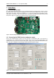
TMC603-EVAL MANUAL (V. 1.01 / April 14th, 2009) 4.3 6 Establishing the connection Thereafter, start the TMC603 Evaluation Software (Figure 3, page 5) on the PC and select the RS232 interface and the associated COM port that is to be used. If you press the “Open” button the connection will established. The connection establishment was successful if the default settings are read automatically. 4.4 Selecting the operating mode Then, enter the operating mode “Block, HallFX, Closed Loop”.
TMC603-EVAL MANUAL (V. 1.01 / April 14th, 2009) 7 3. Connect the evaluation board via null-modem cable with a RS232 port of the PC 4. Start the PC software EVAL603HallFX.EXE 5. Select the COM port (COM1, COM2, …) and push “Open” 6. Select the mode of operation (Block, HallFX, Closed Loop, …) under “Configuration Options” a.
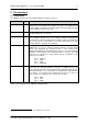
TMC603-EVAL MANUAL (V. 1.01 / April 14th, 2009) 8 5 The Hardware 5.1 Connectors The TMC603 evaluation board is equipped with the following connectors: Name1 Function Power supply X201 This is the connector for power supply. The voltage must be between 12V and 48V DC. The positive pole is marked “12V-48V”. The negative pole is marked “GND”. The board is protected against reverse polarity by a diode (from evaluation board version 1.10).
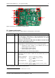
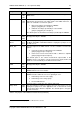
TMC603-EVAL MANUAL (V. 1.01 / April 14th, 2009) 9 Hall sensor Power supply CAN Motor coil output RS232 Figure 4: Connectors of the TMC603 evaluation board 5.2 Jumpers and test pins The TMC603 evaluation board is equipped with the following jumpers and test pins: Jumper Name2 Function BSL X101 If this jumper is plugged, the Bootstrap Loader Mode (BSL) is enabled. The main purpose of BSL Mode is to allow programming/erasing of the Flash and XRAM by using the Infineon USB-2-CAN interface.
TMC603-EVAL MANUAL (V. 1.01 / April 14th, 2009) 10 Jumper Name3 Function U, V, W X105, X106, X107 At these jumpers you can measure phase currents and voltages of the BLDC motor. Filt1, Filt2, Filt3 X108, X109, X110 The microcontroller includes an Analog-to-Digital Converter (ADC) with eight analog input channels. The input signals of the ADC channels 5, 6 and 7 are selectable. You have two options: 1. filtered coil voltages provided by the TMC603 (jumpers plugged in pin 1 and pin 2) 2.
TMC603-EVAL MANUAL (V. 1.01 / April 14th, 2009) 5.3 11 Status Signals The TMC603 evaluation board provides two status LEDs. The green LED (D102) lights up if the power supply is working. The red LED (D203) lights up if an error is occurred by undervoltage of VLS or VCP as well as by short to ground of the power MOS half bridges. 5.4 Dimensions The mechanical dimensions of the TMC603 evaluation board are shown in Figure 5, page 11.
TMC603-EVAL MANUAL (V. 1.01 / April 14th, 2009) 12 6 The PC Software PC software to operate the TMC603 evaluation board is supplied on the TMC TechLibCD or can be downloaded at http://www.trinamic.com. The program can be used with Windows 98, Windows 2000 and Windows XP. To install it, just copy the file “EVAL603HallFX.EXE” to the hard disk of your PC. To run the program, double click the file. 6.1 Overview After starting the software, the main window will be shown (Figure 3).
TMC603-EVAL MANUAL (V. 1.01 / April 14th, 2009) Option Chopper 13 Function Here you can select the chopper mode. This option is available in “Block, Hall Sensor” mode only. The chopper frequency is 20kHz. 1. Low side chopper mode In this chopper mode the low side drivers are chopped only. 2. High side chopper mode In this chopper mode the high side drivers are chopped only. 3. Dual chopper mode Both, the high side drivers and the low side drivers are chopped with the same signal.
TMC603-EVAL MANUAL (V. 1.01 / April 14th, 2009) Option Error 14 Function The status flag “Error” lights up and the motor will stopped if an error has occurred. The TMC603 has three different sources for signaling an error: 1. Undervoltage of the low side supply 2. Undervoltage of the charge pump 3. Short to GND detector In addition the status flag “Error” lights up if you try to ramp up the motor with sine startup and no initialization has been done.
TMC603-EVAL MANUAL (V. 1.01 / April 14th, 2009) 6.2 15 Establishing the connection You can establish a connection to the PC via RS23 interface and via CAN interface. In the following these options shall be described. 6.2.1 Connection via RS232 interface If you use the RS232 interface you need no additional hardware. Before starting the software, the evaluation board should be connected to an RS232 interface of your PC using a null modem cable.
TMC603-EVAL MANUAL (V. 1.01 / April 14th, 2009) 16 If you select the low side chopper mode, the low side drivers are chopped only. In the high side chopper mode the high side drivers are chopped only. If you select the dual chopper mode, the high side drivers and the low side drivers are chopped with the same signal. The option “Invert Hall Sensors” can be selected optionally if the signals of the hall sensors are inverted to the hallFX™ signals.
TMC603-EVAL MANUAL (V. 1.01 / April 14th, 2009) 17 speed control, be sure that the “Duty cycle ref” is unequal to zero. Otherwise the motor will stop. Please note if the speed control is disabled, the motor will start without ramp up. Please take into account that the maximum PWM duty cycle is limited to the value of 93%. This is necessary because the BEMF voltage is incapable of measurement clearly above the PWM duty cycle of 93%. 6.4.
TMC603-EVAL MANUAL (V. 1.01 / April 14th, 2009) 18 PWM duty cycle counts up or down by a value of 1/16 %. You can change these parameters at any time. Please keep in mind to press the “Set” button (Figure 10, page 16). Figure 13: Motor parameters and motor startup parameters (“Block, Hall Sensor”) Thereafter, press the “Start” button and the motor will accelerate up to the defined speed reference (Speed Ref.). Pressing the button “Stop” stops the motor.
TMC603-EVAL MANUAL (V. 1.01 / April 14th, 2009) 6.5 19 An example In this example it is assumed that the QMot Motor QBL4208-41-04-006 is connected to the motor output connector. The evaluation board is connected to an RS232 interface of the PC by using a null modem cable. The board is supplied with 24V (DC). At first, we would like to use the sensorless block commutation with hallFX™ to run the BLDC motor. Please check if the jumpers X212, X213 and X214 are plugged.
TMC603-EVAL MANUAL (V. 1.01 / April 14th, 2009) 20 The initialization for sine startup is not required if you have already started the motor with the same settings in operating mode “Block, HallFX, Closed Loop”. Figure 15: Parameter settings for open loop current control (Example: QMot QBL4208-41-04-006) Figure 16: Parameter settings for hall sensors (Example: QMot QBL4208-41-04-006) Copyright © 2009 TRINAMIC Motion Control GmbH & Co.
TMC603-EVAL MANUAL (V. 1.01 / April 14th, 2009) 21 You can also start the BLDC motor with open loop current control. Please check if the jumpers X212, X213 and X214 are plugged. Select the operating mode “Block, HallFX, Open Loop” and enter the parameters as shown in Figure 15 (page 20). Please keep in mind to press the “Set” buttons. Thereafter, press the “Start” button and the motor will ramp up via open loop current control and will run by using the sensorless BLDC back EMF commutation hallFX™.
TMC603-EVAL MANUAL (V. 1.01 / April 14th, 2009) 22 7 The Firmware 7.1 Updating the firmware The TMC603 evaluation software enables to modify the motor and startup parameters and to control the motor speed. However to update the firmware of the TMC603 evaluation board, the TMCL IDE is required. The TMCL IDE is supplied on the TMC TechLibCD or can be downloaded at http://www.trinamic.com. To install it, just copy the file “TMCL.EXE” to the hard disk of your PC. To run the program, double click the file.
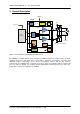
TMC603-EVAL MANUAL (V. 1.01 / April 14th, 2009) 23 8 List of Figures Figure 1: The structure of the TMC603 evaluation board .........................................................................4 Figure 2: Default settings of jumpers for quick start .................................................................................5 Figure 3: The TMC603 Evaluation Software.............................................................................................
TMC603-EVAL MANUAL (V. 1.01 / April 14th, 2009) 24 11 Revision History 11.1 Documentation Revision Version Date Author Description 0.90 24-Oct-08 MW Initial Release 0.91 4-Nov-08 MW Mechanical dimensions added 1.00 18-Feb-09 MW Chapter 6 updated, chapter 7 added, 1 published version 1.01 14-Apr-09 MW Chapter 4 updated, chapter 6 updated, modification note added st Table 7 : Documentation Revisions 11.2 Firmware Revision Version Date Author Description 1.
TMC603-EVAL MANUAL (V. 1.01 / April 14th, 2009) 25 Note: For the first TMC603 evaluation boards (version 1.00 and 1.10), the current measurement is sub-optimal due to a PCB layout mistake. This leads to a noise signal on the current measurement signals of the TMC603. It is fixed by a wire on the first evaluation boards. Some very first boards have been delivered without the fixing wire. Actual boards will be delivered with this fixing wire.