
Datasheet


TMC260/A and TMC261 DATASHEET (Rev. 2.10 / 2016-JUL-14) 49
www.trinamic.com
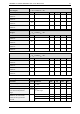
17.3 Thermal Characteristics
Parameter
Symbol
Conditions
Typ
Unit
Thermal resistance bridge
transistor junction to ambient,
one bridge chopping, fixed
polarity
R
THA12
soldered to 2 layer
PCB
88
°K/W
Thermal resistance bridge
transistor junctions to
ambient, two bridges
chopping, fixed polarity
R
THA22
soldered to 2 layer
PCB
68
°K/W
Thermal resistance bridge
transistor junction to ambient,
one bridge chopping, fixed
polarity
R
THA14
soldered to 4 layer
PCB (pessimistic)
84
°K/W
Thermal resistance bridge
transistor junctions to
ambient, two bridges
chopping, fixed polarity
R
THA24
soldered to 4 layer
PCB (pessimistic)
51
°K/W
If the device is to be operated near its maximum thermal limits, care has to be taken to provide a
good thermal design of the PCB layout in order to avoid overheating of the power MOSFETs
integrated into the TMC260 and TMC261. As the TMC26x use discrete MOSFETs, power dissipation in
each MOSFET needs to be looked over carefully.
Worst case power dissipation for the individual MOSFET is in standstill, with one coil operating at the
maximum current, because one full bridge in this case takes over the full current. This scenario can be
avoided with power down current reduction. As the single MOSFET temperatures cannot be
monitored, it is a good practice to react to the temperature pre-warning by reducing motor current,
rather than relying on the overtemperature switch off.
Note
Check MOSFET temperature under worst case conditions not to exceed 150°C, especially for TMC260
and TMC261 in design using a thermal camera to validate your layout.
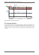
Figure 17.1 One TMC260 operating at 1.4A RMS (2A peak), other TMC260 devices at 1.1A RMS