
User Manual


Table Of Contents
- 1 Features
- 2 First Steps with TMCL
- 3 TMCL and the TMCL-IDE — An Introduction
- 3.1 Binary Command Format
- 3.2 Reply Format
- 3.3 Standalone Applications
- 3.4 The ASCII Interface
- 3.5 TMCL Command Overview
- 3.6 TMCL Commands by Subject
- 3.7 Detailed TMCL Command Descriptions
- 3.7.1 ROR (Rotate Right)
- 3.7.2 ROL (Rotate Left)
- 3.7.3 MST (Motor Stop)
- 3.7.4 MVP (Move to Position)
- 3.7.5 SAP (Set Axis Parameter)
- 3.7.6 GAP (Get Axis Parameter)
- 3.7.7 STAP (Store Axis Parameter)
- 3.7.8 RSAP (Restore Axis Parameter)
- 3.7.9 SGP (Set Global Parameter)
- 3.7.10 GGP (Get Global Parameter)
- 3.7.11 STGP (Store Global Parameter)
- 3.7.12 RSGP (Restore Global Parameter)
- 3.7.13 RFS (Reference Search)
- 3.7.14 SIO (Set Output)
- 3.7.15 GIO (Get Input)
- 3.7.16 CALC (Calculate)
- 3.7.17 COMP (Compare)
- 3.7.18 JC (Jump conditional)
- 3.7.19 JA (Jump always)
- 3.7.20 CSUB (Call Subroutine)
- 3.7.21 RSUB (Return from Subroutine)
- 3.7.22 WAIT (Wait for an Event to occur)
- 3.7.23 STOP (Stop TMCL Program Execution – End of TMCL Program)
- 3.7.24 SCO (Set Coordinate)
- 3.7.25 GCO (Get Coordinate)
- 3.7.26 CCO (Capture Coordinate)
- 3.7.27 ACO (Accu to Coordinate)
- 3.7.28 CALCX (Calculate using the X Register)
- 3.7.29 AAP (Accu to Axis Parameter)
- 3.7.30 AGP (Accu to Global Parameter)
- 3.7.31 CLE (Clear Error Flags)
- 3.7.32 EI (Enable Interrupt)
- 3.7.33 DI (Disable Interrupt)
- 3.7.34 VECT (Define Interrupt Vector)
- 3.7.35 RETI (Return from Interrupt)
- 3.7.36 Customer specific Command Extensions (UF0…UF7 – User Functions)
- 3.7.37 Request Target Position reached Event
- 3.7.38 TMCL Control Commands
- 4 Axis Parameters
- 5 Global Parameters
- 6 Module Specific Hints
- 7 Hints and Tips
- 8 TMCL Programming Techniques and Structure
- 9 Figures Index
- 10 Tables Index
- 11 Supplemental Directives
- 12 Revision History
PD-1160 TMCL
™
Firmware Manual • Firmware Version V1.42 | Document Revision V1.06 • 2018-JAN-09
99 / 113
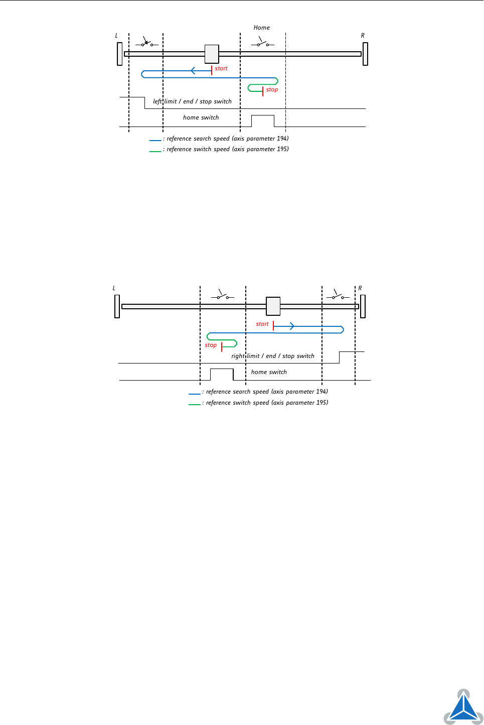
left limit / end / stop switch
L R
start
stop
: reference search speed (axis parameter 194)
: reference switch speed (axis parameter 195)
Home
home switch
Figure 7: Reference search Mode 5
7.1.6 Mode 6
Reference search mode 6 searches the home switch in positive direction. The search direction will be
reversed if the right limit switch is reached. This is shown in figure 8.
Add 128 to the mode number (i.e. set axis parameter #193 to 130) to reverse the polarity of the home
switch input.
L R
right limit / end / stop switch
: reference search speed (axis parameter 194)
: reference switch speed (axis parameter 195)
start
stop
home switch
Figure 8: Reference search Mode 6
7.1.7 Mode 7
Reference search mode 7 searches the home switch in positive direction, ignoring the limit switch inputs.
It is recommende mainly for use with a circular axis. The exact middle of the switch will be found and used
as the zero point. Figure 9 illustrates this.
Add 128 to the mode number (i.e. set axis parameter #193 to 131) to reverse the polarity of the home
switch input.
©2018 TRINAMIC Motion Control GmbH & Co. KG, Hamburg, Germany
Terms of delivery and rights to technical change reserved.
Download newest version at www.trinamic.com