
User Manual


Table Of Contents
- 1 Features
- 2 First Steps with TMCL
- 3 TMCL and the TMCL-IDE — An Introduction
- 3.1 Binary Command Format
- 3.2 Reply Format
- 3.3 Standalone Applications
- 3.4 The ASCII Interface
- 3.5 TMCL Command Overview
- 3.6 TMCL Commands by Subject
- 3.7 Detailed TMCL Command Descriptions
- 3.7.1 ROR (Rotate Right)
- 3.7.2 ROL (Rotate Left)
- 3.7.3 MST (Motor Stop)
- 3.7.4 MVP (Move to Position)
- 3.7.5 SAP (Set Axis Parameter)
- 3.7.6 GAP (Get Axis Parameter)
- 3.7.7 STAP (Store Axis Parameter)
- 3.7.8 RSAP (Restore Axis Parameter)
- 3.7.9 SGP (Set Global Parameter)
- 3.7.10 GGP (Get Global Parameter)
- 3.7.11 STGP (Store Global Parameter)
- 3.7.12 RSGP (Restore Global Parameter)
- 3.7.13 RFS (Reference Search)
- 3.7.14 SIO (Set Output)
- 3.7.15 GIO (Get Input)
- 3.7.16 CALC (Calculate)
- 3.7.17 COMP (Compare)
- 3.7.18 JC (Jump conditional)
- 3.7.19 JA (Jump always)
- 3.7.20 CSUB (Call Subroutine)
- 3.7.21 RSUB (Return from Subroutine)
- 3.7.22 WAIT (Wait for an Event to occur)
- 3.7.23 STOP (Stop TMCL Program Execution – End of TMCL Program)
- 3.7.24 SCO (Set Coordinate)
- 3.7.25 GCO (Get Coordinate)
- 3.7.26 CCO (Capture Coordinate)
- 3.7.27 ACO (Accu to Coordinate)
- 3.7.28 CALCX (Calculate using the X Register)
- 3.7.29 AAP (Accu to Axis Parameter)
- 3.7.30 AGP (Accu to Global Parameter)
- 3.7.31 CLE (Clear Error Flags)
- 3.7.32 EI (Enable Interrupt)
- 3.7.33 DI (Disable Interrupt)
- 3.7.34 VECT (Define Interrupt Vector)
- 3.7.35 RETI (Return from Interrupt)
- 3.7.36 Customer specific Command Extensions (UF0…UF7 – User Functions)
- 3.7.37 Request Target Position reached Event
- 3.7.38 TMCL Control Commands
- 4 Axis Parameters
- 5 Global Parameters
- 6 Module Specific Hints
- 7 Hints and Tips
- 8 TMCL Programming Techniques and Structure
- 9 Figures Index
- 10 Tables Index
- 11 Supplemental Directives
- 12 Revision History
PD-1160 TMCL
™
Firmware Manual • Firmware Version V1.42 | Document Revision V1.06 • 2018-JAN-09
94 / 113
•
To read out or to change the position value of the encoder use axis parameter #216. To read out the
position of the internal encoder use GAP 216, 0. The encoder position register can also be changed
using command SAP 216, 0, <n>, with n = -2147483648 . . . 2147483647.
• Axis parameter #217 is used to change the encoder settings. This also includes the prescaler of the
encoder. The prescaler is used to match motor resolution and encoder resolution.
•
The motor can be stopped automatically if motor position and encoder position differ too much
(deviation error). This can be set using axis parameter #218 (maximum deviation). Setting this
parameter to 0 turns off this feature.
Using the prescaler the encoder counter increments / decrements can be aligned to the position (microstep)
counter. This is essential when using the deviation error supervision (axis parameter #218) and simplifies
encoder counter versus position/microstep counter comparisons (1:1).
number_of_microsteps_per_motor_rotation = prescaler · encoder_ticks_per_rotation
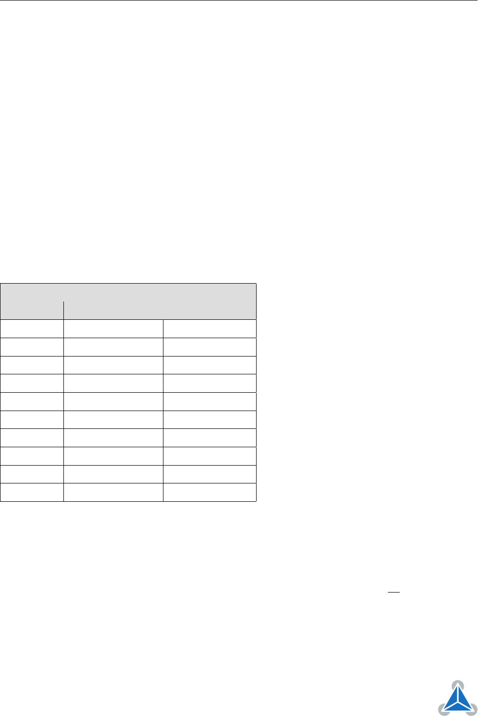
Table 21 shows a subset of encoder prescaler values that can be selected. Other values can also be used,
but the bits 2. . . 4 must not be used for the prescaler because they are needed to select special encoder
functions.
If you are not sure about the resolution of the encoder, use a prescaler of 1 (SAP 217, 0, 512) and then let
the motor run exactly one round to see how far the encoder is counting then.
Encoder Prescaler Values
Value (<p>) Resulting prescaler SAP command
64 0.125 SAP 217, 0, 64
128 0.25 SAP 217, 0, 128
256 0.5 SAP 217, 0, 256
512 1 SAP 217, 0, 512
1024 2 SAP 217, 0, 1024
2048 4 SAP 217, 0, 2048
4096 8 SAP 217, 0, 4096
8192 16 SAP 217, 0, 8192
16384 32 SAP 217, 0, 16384
32768 64 SAP 217, 0, 32768
Table 21: Encoder Prescaler Values
Encoder resolutions are often (but not always) given in lines per rotation (lpr) by the manufaturer of the
encoder. Convert this value to counts per rotation (cpr) by multiplying it by four (because of the quadrature
interface).
Other values than those given in table 21 are also possible. The resulting prescaler is
p
512
. But please bear
in mind not to use bits 2, 3, and 4 of the value, as they are reserved for other functions.
Not all encoder resolutions can be matched with the motor microstep resolution. We recommend to
choose an encoder with a binary resolution (like 512, 2048, 4096, 32768) when selecting an encoder. There
is always a suitable prescaler for such encoders.
©2018 TRINAMIC Motion Control GmbH & Co. KG, Hamburg, Germany
Terms of delivery and rights to technical change reserved.
Download newest version at www.trinamic.com