
User Manual


Table Of Contents
- 1 Features
- 2 First Steps with TMCL
- 3 TMCL and the TMCL-IDE — An Introduction
- 3.1 Binary Command Format
- 3.2 Reply Format
- 3.3 Standalone Applications
- 3.4 The ASCII Interface
- 3.5 TMCL Command Overview
- 3.6 TMCL Commands by Subject
- 3.7 Detailed TMCL Command Descriptions
- 3.7.1 ROR (Rotate Right)
- 3.7.2 ROL (Rotate Left)
- 3.7.3 MST (Motor Stop)
- 3.7.4 MVP (Move to Position)
- 3.7.5 SAP (Set Axis Parameter)
- 3.7.6 GAP (Get Axis Parameter)
- 3.7.7 STAP (Store Axis Parameter)
- 3.7.8 RSAP (Restore Axis Parameter)
- 3.7.9 SGP (Set Global Parameter)
- 3.7.10 GGP (Get Global Parameter)
- 3.7.11 STGP (Store Global Parameter)
- 3.7.12 RSGP (Restore Global Parameter)
- 3.7.13 RFS (Reference Search)
- 3.7.14 SIO (Set Output)
- 3.7.15 GIO (Get Input)
- 3.7.16 CALC (Calculate)
- 3.7.17 COMP (Compare)
- 3.7.18 JC (Jump conditional)
- 3.7.19 JA (Jump always)
- 3.7.20 CSUB (Call Subroutine)
- 3.7.21 RSUB (Return from Subroutine)
- 3.7.22 WAIT (Wait for an Event to occur)
- 3.7.23 STOP (Stop TMCL Program Execution – End of TMCL Program)
- 3.7.24 SCO (Set Coordinate)
- 3.7.25 GCO (Get Coordinate)
- 3.7.26 CCO (Capture Coordinate)
- 3.7.27 ACO (Accu to Coordinate)
- 3.7.28 CALCX (Calculate using the X Register)
- 3.7.29 AAP (Accu to Axis Parameter)
- 3.7.30 AGP (Accu to Global Parameter)
- 3.7.31 CLE (Clear Error Flags)
- 3.7.32 EI (Enable Interrupt)
- 3.7.33 DI (Disable Interrupt)
- 3.7.34 VECT (Define Interrupt Vector)
- 3.7.35 RETI (Return from Interrupt)
- 3.7.36 Customer specific Command Extensions (UF0…UF7 – User Functions)
- 3.7.37 Request Target Position reached Event
- 3.7.38 TMCL Control Commands
- 4 Axis Parameters
- 5 Global Parameters
- 6 Module Specific Hints
- 7 Hints and Tips
- 8 TMCL Programming Techniques and Structure
- 9 Figures Index
- 10 Tables Index
- 11 Supplemental Directives
- 12 Revision History
PD-1160 TMCL
™
Firmware Manual • Firmware Version V1.42 | Document Revision V1.06 • 2018-JAN-09
56 / 113
3.7.25 GCO (Get Coordinate)
Using this command previously stored coordinate can be read back. In standalone mode the requested
value is copied to the accumulator register for further processing purposes such as conditional jumps.
In direct mode, the value is only output in the value field of the reply, without affecting the accumulator.
Depending on the global parameter 84, the coordinates are only stored in RAM or also stored in the
EEPROM and copied back on startup (with the default setting the coordinates are stored in RAM only).
Note
Coordinate #0 is always stored in RAM only.
Internal function:
the desired value is read out of the internal coordinate array, copied to the accumulator
register and – in direct mode – returned in the value field of the reply.
Related commands: SCO, CCO, ACO, MVP COORD.
Mnemonic: GCO <coordinate number>, <motor number>
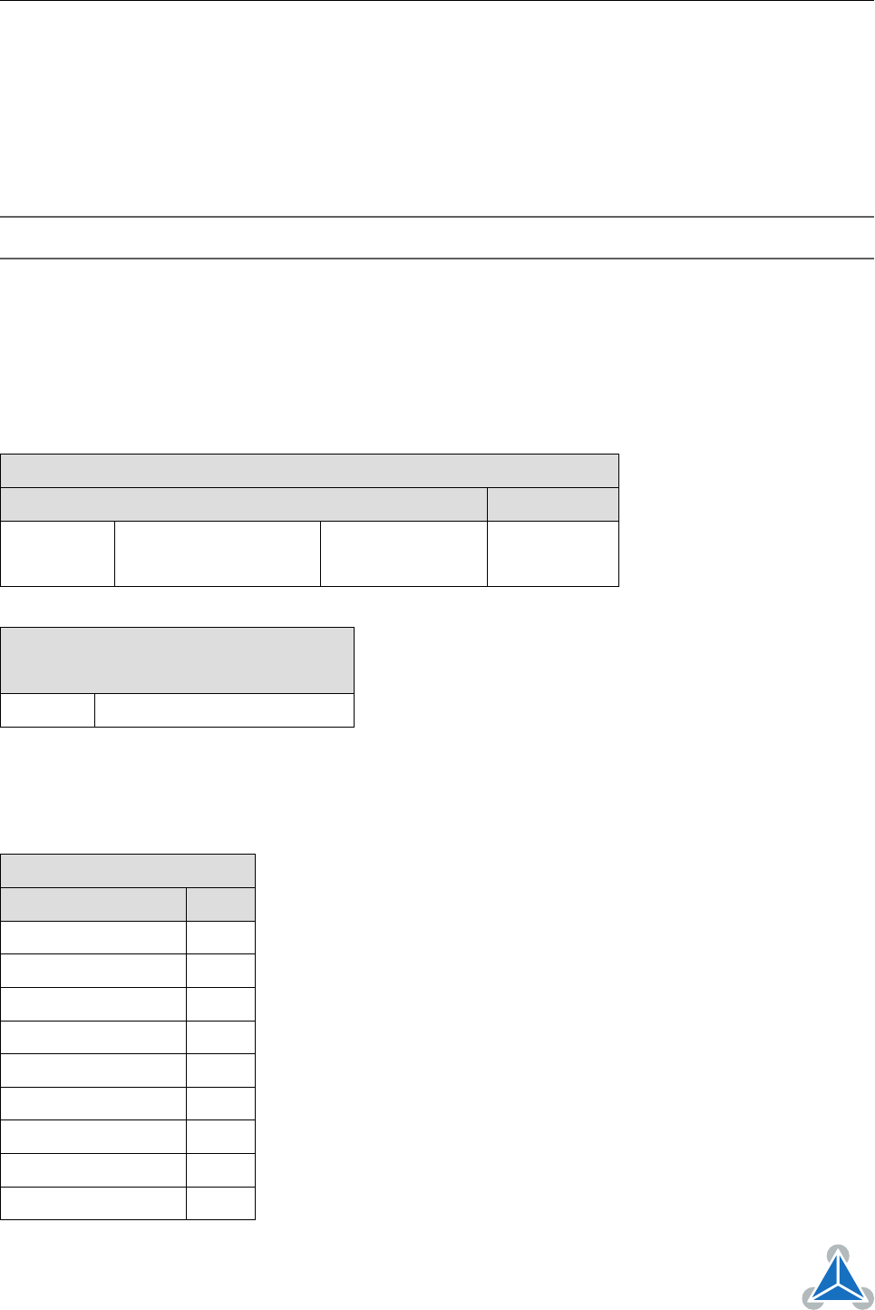
Binary Representation
Instruction Type Motor/Bank Value
31 <coordinate number> <motor number> 0 (don’t care)
0. . . 20 0
Reply in Direct Mode
Status Value
100 - OK value read by this command
Example
Get coordinate #1 of motor #0.
Mnemonic: GCO 1, 0
Binary Form of GCO 1, 0
Field Value
Target address 01
h
Instruction number 1F
h
Type 01
h
Motor/Bank 00
h
Value (Byte 3) 00
h
Value (Byte 2) 00
h
Value (Byte 1) 00
h
Value (Byte 0) 00
h
Checksum 21
h
©2018 TRINAMIC Motion Control GmbH & Co. KG, Hamburg, Germany
Terms of delivery and rights to technical change reserved.
Download newest version at www.trinamic.com