
User Manual


Table Of Contents
- 1 Features
- 2 First Steps with TMCL
- 3 TMCL and the TMCL-IDE — An Introduction
- 3.1 Binary Command Format
- 3.2 Reply Format
- 3.3 Standalone Applications
- 3.4 The ASCII Interface
- 3.5 TMCL Command Overview
- 3.6 TMCL Commands by Subject
- 3.7 Detailed TMCL Command Descriptions
- 3.7.1 ROR (Rotate Right)
- 3.7.2 ROL (Rotate Left)
- 3.7.3 MST (Motor Stop)
- 3.7.4 MVP (Move to Position)
- 3.7.5 SAP (Set Axis Parameter)
- 3.7.6 GAP (Get Axis Parameter)
- 3.7.7 STAP (Store Axis Parameter)
- 3.7.8 RSAP (Restore Axis Parameter)
- 3.7.9 SGP (Set Global Parameter)
- 3.7.10 GGP (Get Global Parameter)
- 3.7.11 STGP (Store Global Parameter)
- 3.7.12 RSGP (Restore Global Parameter)
- 3.7.13 RFS (Reference Search)
- 3.7.14 SIO (Set Output)
- 3.7.15 GIO (Get Input)
- 3.7.16 CALC (Calculate)
- 3.7.17 COMP (Compare)
- 3.7.18 JC (Jump conditional)
- 3.7.19 JA (Jump always)
- 3.7.20 CSUB (Call Subroutine)
- 3.7.21 RSUB (Return from Subroutine)
- 3.7.22 WAIT (Wait for an Event to occur)
- 3.7.23 STOP (Stop TMCL Program Execution – End of TMCL Program)
- 3.7.24 SCO (Set Coordinate)
- 3.7.25 GCO (Get Coordinate)
- 3.7.26 CCO (Capture Coordinate)
- 3.7.27 ACO (Accu to Coordinate)
- 3.7.28 CALCX (Calculate using the X Register)
- 3.7.29 AAP (Accu to Axis Parameter)
- 3.7.30 AGP (Accu to Global Parameter)
- 3.7.31 CLE (Clear Error Flags)
- 3.7.32 EI (Enable Interrupt)
- 3.7.33 DI (Disable Interrupt)
- 3.7.34 VECT (Define Interrupt Vector)
- 3.7.35 RETI (Return from Interrupt)
- 3.7.36 Customer specific Command Extensions (UF0…UF7 – User Functions)
- 3.7.37 Request Target Position reached Event
- 3.7.38 TMCL Control Commands
- 4 Axis Parameters
- 5 Global Parameters
- 6 Module Specific Hints
- 7 Hints and Tips
- 8 TMCL Programming Techniques and Structure
- 9 Figures Index
- 10 Tables Index
- 11 Supplemental Directives
- 12 Revision History
PD-1160 TMCL
™
Firmware Manual • Firmware Version V1.42 | Document Revision V1.06 • 2018-JAN-09
42 / 113
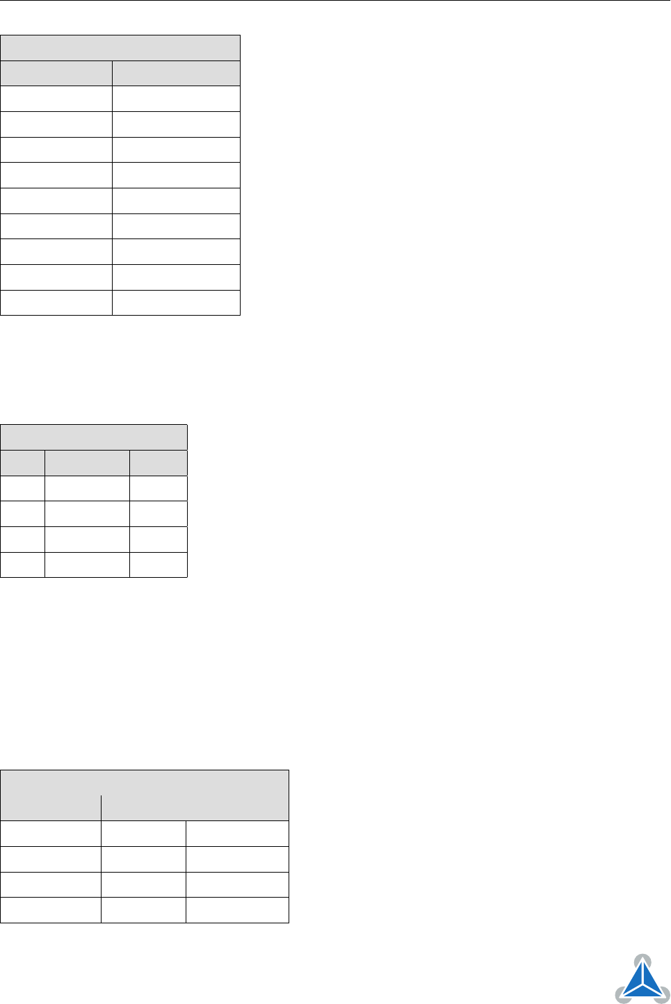
Reply (Status=no error, Value=302)
Field Value
Host address 02
h
Target address 01
h
Status 64
h
Instruction 0F
h
Value (Byte 3) 00
h
Value (Byte 2) 00
h
Value (Byte 1) 01
h
Value (Byte 0) 2E
h
Checksum A5
h
Bank 0 – Digital Inputs
The analog input lines can be read as digital or analog inputs at the same time. The digital input states can
be accessed in bank 0.
Digital Inputs in Bank 0
Port Command Range
IN0 GIO 0, 0 0/1
IN1 GIO 1, 0 0/1
IN2 GIO 2, 0 0/1
IN3 GIO 3, 0 0/1
Special case: GIO 255, 0 reads all general purpose inputs simulataneously and puts the result into the lower
eight bits of the accumulator register.
Special case: GIO 11, 0 checks if the sensOstep™ encoder is near its absolute zero position.
Bank 1 – Analog Inputs
The analog input lines can be read back as digital or analog inputs at the same time. The analog values
can be accessed in bank 1.
Analog Inputs in Bank 1
Port Command Range / Units
IN0 GIO 0, 1 0. . . 4095
IN1 GIO 1, 1 0. . . 4095
Voltage GIO 8, 1 [1/10V]
Temperature GIO 9, 1 [°C]
©2018 TRINAMIC Motion Control GmbH & Co. KG, Hamburg, Germany
Terms of delivery and rights to technical change reserved.
Download newest version at www.trinamic.com