
User Manual


Table Of Contents
- 1 Features
- 2 First Steps with TMCL
- 3 TMCL and the TMCL-IDE — An Introduction
- 3.1 Binary Command Format
- 3.2 Reply Format
- 3.3 Standalone Applications
- 3.4 The ASCII Interface
- 3.5 TMCL Command Overview
- 3.6 TMCL Commands by Subject
- 3.7 Detailed TMCL Command Descriptions
- 3.7.1 ROR (Rotate Right)
- 3.7.2 ROL (Rotate Left)
- 3.7.3 MST (Motor Stop)
- 3.7.4 MVP (Move to Position)
- 3.7.5 SAP (Set Axis Parameter)
- 3.7.6 GAP (Get Axis Parameter)
- 3.7.7 STAP (Store Axis Parameter)
- 3.7.8 RSAP (Restore Axis Parameter)
- 3.7.9 SGP (Set Global Parameter)
- 3.7.10 GGP (Get Global Parameter)
- 3.7.11 STGP (Store Global Parameter)
- 3.7.12 RSGP (Restore Global Parameter)
- 3.7.13 RFS (Reference Search)
- 3.7.14 SIO (Set Output)
- 3.7.15 GIO (Get Input)
- 3.7.16 CALC (Calculate)
- 3.7.17 COMP (Compare)
- 3.7.18 JC (Jump conditional)
- 3.7.19 JA (Jump always)
- 3.7.20 CSUB (Call Subroutine)
- 3.7.21 RSUB (Return from Subroutine)
- 3.7.22 WAIT (Wait for an Event to occur)
- 3.7.23 STOP (Stop TMCL Program Execution – End of TMCL Program)
- 3.7.24 SCO (Set Coordinate)
- 3.7.25 GCO (Get Coordinate)
- 3.7.26 CCO (Capture Coordinate)
- 3.7.27 ACO (Accu to Coordinate)
- 3.7.28 CALCX (Calculate using the X Register)
- 3.7.29 AAP (Accu to Axis Parameter)
- 3.7.30 AGP (Accu to Global Parameter)
- 3.7.31 CLE (Clear Error Flags)
- 3.7.32 EI (Enable Interrupt)
- 3.7.33 DI (Disable Interrupt)
- 3.7.34 VECT (Define Interrupt Vector)
- 3.7.35 RETI (Return from Interrupt)
- 3.7.36 Customer specific Command Extensions (UF0…UF7 – User Functions)
- 3.7.37 Request Target Position reached Event
- 3.7.38 TMCL Control Commands
- 4 Axis Parameters
- 5 Global Parameters
- 6 Module Specific Hints
- 7 Hints and Tips
- 8 TMCL Programming Techniques and Structure
- 9 Figures Index
- 10 Tables Index
- 11 Supplemental Directives
- 12 Revision History
PD-1160 TMCL
™
Firmware Manual • Firmware Version V1.42 | Document Revision V1.06 • 2018-JAN-09
40 / 113
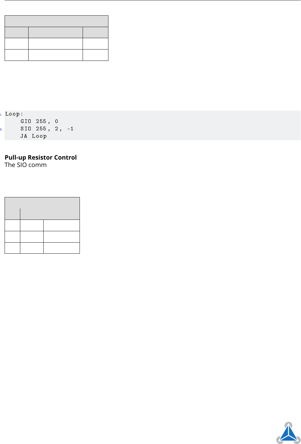
Digital Outputs in Bank 2
Port Command Range
OUT0 SIO 0, 2, <value> 0/1
OUT1 SIO 1, 2, <value> 0/1
Special case: SIO 255, 2, <x> can be used to change all general purpose digital output lines simulaneously.
The value <x> will then be interpreted as a bit vector where each of the lower eight bits represents one of
the digital outputs. So the range for <x> is 0. . . 255. The value <x> can also be -1. In this case, the value will
be taken from the accumulator register. The following program can be used to copy the states of the input
lines to the output lines:
1
Loop:
GIO 255, 0
3
SIO 255, 2, -1
JA Loop
Pull-up Resistor Control
The SIO command can also be used to program the pull-up resistors of the STOP_L, STOP_R and HOME
inputs. All three pull-up resistors can seperately be switched off or on. For this purpose, use the command
SIO 0, 0, <x> where the value <x> is a bit vector. The following table shows the meaning of the different
bits:
Pull-up Resistor Control
Bit Value Input
0 1 STOP_L
1 2 STOP_R
2 4 HOME
A bit that is set switches on the corresponding pull-up resistor. So for example SIO 0, 0, 0 turns off all
pull-up resistors, and SIO 0, 0, 7 turns on all pull-up-resistors. All pull-up resistors are on by default.
©2018 TRINAMIC Motion Control GmbH & Co. KG, Hamburg, Germany
Terms of delivery and rights to technical change reserved.
Download newest version at www.trinamic.com