
User Manual


Table Of Contents
- 1 Features
- 2 First Steps with TMCL
- 3 TMCL and the TMCL-IDE — An Introduction
- 3.1 Binary Command Format
- 3.2 Reply Format
- 3.3 Standalone Applications
- 3.4 The ASCII Interface
- 3.5 TMCL Command Overview
- 3.6 TMCL Commands by Subject
- 3.7 Detailed TMCL Command Descriptions
- 3.7.1 ROR (Rotate Right)
- 3.7.2 ROL (Rotate Left)
- 3.7.3 MST (Motor Stop)
- 3.7.4 MVP (Move to Position)
- 3.7.5 SAP (Set Axis Parameter)
- 3.7.6 GAP (Get Axis Parameter)
- 3.7.7 STAP (Store Axis Parameter)
- 3.7.8 RSAP (Restore Axis Parameter)
- 3.7.9 SGP (Set Global Parameter)
- 3.7.10 GGP (Get Global Parameter)
- 3.7.11 STGP (Store Global Parameter)
- 3.7.12 RSGP (Restore Global Parameter)
- 3.7.13 RFS (Reference Search)
- 3.7.14 SIO (Set Output)
- 3.7.15 GIO (Get Input)
- 3.7.16 CALC (Calculate)
- 3.7.17 COMP (Compare)
- 3.7.18 JC (Jump conditional)
- 3.7.19 JA (Jump always)
- 3.7.20 CSUB (Call Subroutine)
- 3.7.21 RSUB (Return from Subroutine)
- 3.7.22 WAIT (Wait for an Event to occur)
- 3.7.23 STOP (Stop TMCL Program Execution – End of TMCL Program)
- 3.7.24 SCO (Set Coordinate)
- 3.7.25 GCO (Get Coordinate)
- 3.7.26 CCO (Capture Coordinate)
- 3.7.27 ACO (Accu to Coordinate)
- 3.7.28 CALCX (Calculate using the X Register)
- 3.7.29 AAP (Accu to Axis Parameter)
- 3.7.30 AGP (Accu to Global Parameter)
- 3.7.31 CLE (Clear Error Flags)
- 3.7.32 EI (Enable Interrupt)
- 3.7.33 DI (Disable Interrupt)
- 3.7.34 VECT (Define Interrupt Vector)
- 3.7.35 RETI (Return from Interrupt)
- 3.7.36 Customer specific Command Extensions (UF0…UF7 – User Functions)
- 3.7.37 Request Target Position reached Event
- 3.7.38 TMCL Control Commands
- 4 Axis Parameters
- 5 Global Parameters
- 6 Module Specific Hints
- 7 Hints and Tips
- 8 TMCL Programming Techniques and Structure
- 9 Figures Index
- 10 Tables Index
- 11 Supplemental Directives
- 12 Revision History
PD-1160 TMCL
™
Firmware Manual • Firmware Version V1.42 | Document Revision V1.06 • 2018-JAN-09
20 / 113
in the accumulator. The X register can be used as an additional memory when doing calculations. It can be
loaded from the accumulator.
When a command that reads a value is executed in direct mode the accumulator will not be affected.
This means that while a TMCL program is running on the module (standalone mode), a host can still
send commands like GAP and GGP to the module (e.g. to query the actual position of the motor) without
affecting the flow of the TMCL program running on the module.
3.6.6 Interrupt Processing Commands
TMCL also contains functions for a simple way of interrupt processing. Using interrupts, many tasks can
be programmed in an easier way.
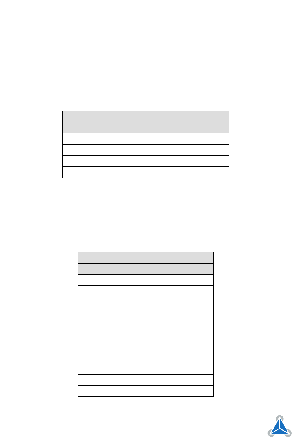
The following commands are use to define and handle interrupts:
Interrupt Processing Commands
Mnemonic Command number Meaning
EI 25 Enable interrupt
DI 26 Disable interrupt
VECT 37 Set interrupt vector
RETI 38 Return from interrupt
Table 11: Interrupt Processing Commands
3.6.6.1 Interrupt Types
There are many different interrupts in TMCL, like timer interrupts, stop switch interrupts, position reached
interrupts, and input pin change interrupts. Each of these interrupts has its own interrupt vector. Each
interrupt vector is identified by its interrupt number. Please use the TMCL include file Interrupts.inc in
order to have symbolic constants for the interrupt numbers. Table 12 show all interrupts that are available
on the PD-1160.
Interrupt Vectors
Interrupt number Interrupt type
0 Timer 0
1 Timer 1
2 Timer 2
3 Target position reached 0
15 stallGuard axis 0
21 Deviation axis 0
27 Left stop switch 0
28 Right stop switch 0
39 Input change 0
40 Input change 1
255 Global interrupts
Table 12: Interrupt Vectors
©2018 TRINAMIC Motion Control GmbH & Co. KG, Hamburg, Germany
Terms of delivery and rights to technical change reserved.
Download newest version at www.trinamic.com