
User Manual
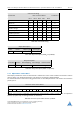

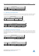
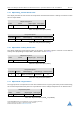
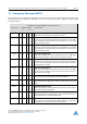
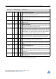
Table Of Contents
- 1 Preface
- 2 Communication
- 3 Communication Area
- 3.1 Detailed Object Specifications
- 3.1.1 Object 1000h: Device Type
- 3.1.2 Object 1001h: Error Register
- 3.1.3 Object 1005h: COB-ID SYNC Message
- 3.1.4 Object 1008h: Manufacturer Device Name
- 3.1.5 Object 1009h: Manufacturer Hardware Version
- 3.1.6 Object 100Ah: Manufacturer Software Version
- 3.1.7 Object 100Ch: Guard Time
- 3.1.8 Object 100Dh: Life Time Factor
- 3.1.9 Object 1010h: Store Parameters
- 3.1.10 Object 1011h: Restore Parameters
- 3.1.11 Object 1014h: COB-ID Emergency Object
- 3.1.12 Object 1015h: Inhibit Time EMCY
- 3.1.13 Object 1016h: Consumer Heartbeat Time
- 3.1.14 Object 1017h: Producer Heartbeat Time
- 3.1.15 Object 1018h: Identity Object
- 3.1.16 Object 1029h: Error Behaviour
- 3.1.17 Objects 1400h – 1403h: Receive PDO Communication Parameter
- 3.1.18 Objects 1600h – 1603h: Receive PDO Mapping Parameter
- 3.1.19 Objects 1800h – 1803h: Transmit PDO Communication Parameter
- 3.1.20 Objects 1A00h – 1A03h: Transmit PDO Mapping Parameter
- 3.1 Detailed Object Specifications
- 4 Manufacturer specific Area
- 4.1 Objects related to coolStep
- 4.2 Detailed Object Specifications
- 4.2.1 Object 2000h: Microstep Resolution
- 4.2.2 Object 2001h: Fullstep Resolution
- 4.2.3 Object 2002h: Brake Delay Times
- 4.2.4 Object 2003h: Maximum Current
- 4.2.5 Object 2004h: Standby Current
- 4.2.6 Object 2005h: Limit Switches
- 4.2.7 Object 200Ah: Enable Drive Delay Time
- 4.2.8 Object 200Bh: Encoder Parameters
- 4.2.9 Object 200Ch: Brake Current Feed
- 4.2.10 Object 2010h: Profile Start Velocity
- 4.2.11 Object 2011h: Profile A1
- 4.2.12 Object 2012h: Profile V1
- 4.2.13 Object 2013h: Profile D1
- 4.2.14 Object 2015h: Ramp Wait Time
- 4.2.15 Object 2089h: Setting Delay
- 4.2.16 Object 208Ch: Velocity Dimension Index
- 4.2.17 Object 208Eh: Acceleration Dimension Index
- 4.2.18 Object 2092h: Chopper Blank Time
- 4.2.19 Object 2093h: Chopper Mode
- 4.2.20 Object 2094h: Chopper Hysteresis Decrement
- 4.2.21 Object 2095h: Chopper Hysteresis End
- 4.2.22 Object 2096h: Chopper Hysteresis Start
- 4.2.23 Object 2097h: Chopper Off Time
- 4.2.24 Object 2098h: Smart Energy Current Minimum
- 4.2.25 Object 2099h: Smart Energy Current Down Step
- 4.2.26 Object 209Ah: Smart Energy Hysteresis
- 4.2.27 Object 209Bh: Smart Energy Current Up Step
- 4.2.28 Object 209Ch: Smart Energy Hysteresis Start
- 4.2.29 Object 209Dh: Smart Energy Filter Enable
- 4.2.30 Object 209Eh: stallGuard2 Threshold
- 4.2.31 Object 20A1h: Short Protection Disable
- 4.2.32 Object 20A4h: Stop on Stall
- 4.2.33 Object 20A5h: Smart Energy Threshold Speed
- 4.2.34 Object 20B0h: PWM Threshold Speed
- 4.2.35 Object 20B1h: PWM Gradient
- 4.2.36 Object 20B2h: PWM Amplitude
- 4.2.37 Object 20B3h: dcStep Minimum Speed
- 4.2.38 Object 20B4h: dcStep Time
- 4.2.39 Object 20B5h: dcStep stallGuard
- 4.2.40 Object 20B6h: Fullstep Threshold Speed
- 4.2.41 Object 20B7h: High Speed Chopper Mode
- 4.2.42 Object 20B8h: High Speed Fullstep Mode
- 4.2.43 Object 20B9h: Power Down Ramp
- 4.2.44 Object 2100h: Home Offset Display
- 4.2.45 Object 2101h: Actual Load Value
- 4.2.46 Object 2102h: Driver Error Flags
- 4.2.47 Object 2107h: Microstep Resolution Display
- 4.2.48 Object 210Bh: Step Counter
- 4.2.49 Object 2121h: PWM Scale Value
- 4.2.50 Object 2122h: Measured Velocity
- 4.2.51 Object 2700h: TMCL Direct Communication
- 4.2.52 Object 2701h: Manufacturer Specific Mode
- 4.2.53 Object 2702h: Device Digital Inputs
- 4.2.54 Object 2703h: Device Digital Outputs
- 4.2.55 Object 2704h: CAN Bit Rate
- 4.2.56 Object 2705h: Node ID
- 4.2.57 Object 2706h: Store
- 4.2.58 Object 2707h: CAN Bit Rate Load
- 4.2.59 Object 2708h: Node ID Load
- 4.2.60 Object 270Eh: Device Analog Inputs
- 4.2.61 Object 2710h: Pull-up Resistors
- 5 Profile specific Area
- 5.1 Detailed Object Specifications
- 5.1.1 Object 605Ah: Quick Stop Option Code
- 5.1.2 Object 605Bh: Shutdown Option Code
- 5.1.3 Object 605Ch: Disable Operation Option Code
- 5.1.4 Object 605Dh: Halt Option Code
- 5.1.5 Object 605Eh: Fault Reaction Option Code
- 5.1.6 Object 6060h: Modes of Operation
- 5.1.7 Object 6061h: Modes of Operation Display
- 5.1.8 Object 606Ah: Sensor Selection Code
- 5.1.9 Object 608Fh: Position Encoder Resolution
- 5.1.10 Object 60FDh: Digital Inputs
- 5.1.11 Object 6502h: Supported Drive Modes
- 5.1 Detailed Object Specifications
- 6 Profile Position Mode
- 6.1 Detailed Object Specifications
- 6.1.1 Object 6040h: Control Word
- 6.1.2 Object 6041h: Status Word
- 6.1.3 Object 6062h: Position Demand Value
- 6.1.4 Object 6063h: Position Actual Internal Value
- 6.1.5 Object 6064h: Position Actual Value
- 6.1.6 Object 6065h: Following Error Window
- 6.1.7 Object 6067h: Position Window
- 6.1.8 Object 6068h: Position Window Time
- 6.1.9 Object 606Ch: Velocity Actual Value
- 6.1.10 Object 607Ah: Target Position
- 6.1.11 Object 607Dh: Software Position Limit
- 6.1.12 Object 6081h: Profile Velocity
- 6.1.13 Object 6082h: End Velocity
- 6.1.14 Object 6083h: Profile Acceleration
- 6.1.15 Object 6084h: Profile Deceleration
- 6.1.16 Object 6085h: Quick Stop Deceleration
- 6.1.17 Object 60F2h: Positioning Option Code
- 6.2 How to move a Motor in pp Mode
- 6.1 Detailed Object Specifications
- 7 Profile Velocity Mode
- 7.1 Detailed Object Specifications
- 7.1.1 Object 6040h: Control Word
- 7.1.2 Object 6041h: Status Word
- 7.1.3 Object 6062h: Position Demand Value
- 7.1.4 Object 6063h: Position Actual Internal Value
- 7.1.5 Object 6064h: Position Actual Value
- 7.1.6 Object 6065h: Following Error Window
- 7.1.7 Object 606Ch: Velocity Actual Value
- 7.1.8 Object 607Dh: Software Position Limit
- 7.1.9 Object 6083h: Profile Acceleration
- 7.1.10 Object 6085h: Quick Stop Deceleration
- 7.1.11 Object 60FFh: Target Velocity
- 7.2 How to move a Motor in pv Mode
- 7.1 Detailed Object Specifications
- 8 Homing Mode
- 8.1 Homing Methods
- 8.1.1 Homing Method 1: Homing on negative Limit Switch and Index Pulse
- 8.1.2 Homing Method 2: Homing on positive Limit Switch and Index Pulse
- 8.1.3 Homing Method 3: Homing on positive Home Switch and Index Pulse
- 8.1.4 Homing Method 5: Homing on negative Home Switch and Index Pulse
- 8.1.5 Homing Method 17, 18, 19, and 21: Homing without Index Pulse
- 8.1.6 Homing Method 33 and 34: Homing on next Index Pulse
- 8.1.7 Homing Method 35: Current Position as Home Position
- 8.2 Detailed Object Specifications
- 8.3 How to start a Homing in hm Mode
- 8.1 Homing Methods
- 9 Cyclic synchonous Position Mode
- 9.1 Detailed Object Specifications
- 9.1.1 Object 6040h: Control Word
- 9.1.2 Object 6041h: Status Word
- 9.1.3 Object 6062h: Position Demand Value
- 9.1.4 Object 6063h: Position Actual Internal Value
- 9.1.5 Object 6064h: Position Actual Value
- 9.1.6 Object 606Ch: Velocity Actual Value
- 9.1.7 Object 607Ah: Target Position
- 9.1.8 Object 607Dh: Software Position Limit
- 9.1.9 Object 60B0h: Position Offset
- 9.1.10 Object 60C2h: Interpolation Time Period
- 9.1 Detailed Object Specifications
- 10 Emergency Messages (EMCY)
- 11 Figures Index
- 12 Tables Index
- 13 Supplemental Directives
- 14 Revision History
PD42-1241 CANopen
®
Firmware Manual • Firmware Version V3.21 | Document Revision V1.00 • 2018-MAY-03
102 / 117
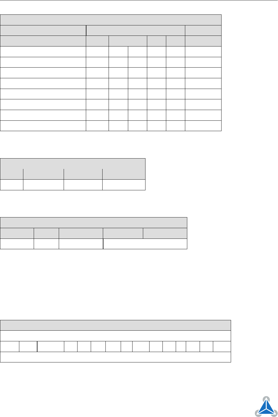
Command Coding
Command Bits of Control Word Transitions
Bit 7 Bit 3 Bit 2 Bit 1 Bit 0
Shutdown 0 x 1 1 0 2,6,8
Switch on 0 0 1 1 1 3
Switch on & enable operation 0 1 1 1 1 3, 4
Disable voltage 0 x x 0 x 7,9,10,12
Quick stop 0 x 0 1 x 7,10,11
Disable operation 0 0 1 1 1 5
Enable operation 0 1 1 1 1 4, 16
Fault reset 0-to-1 x x x x 15
Table 305: Command Coding
Object Description
Index Name Object Type Data Type
6040
h
Controlword Variable UNSIGNED16
Table 306: Object Description (6040
h
in csp Mode)
Entry Description
Sub-index Access PDO Mapping Value Range Default Value
0 rw see CiA402-3 See command coding above.
Table 307: Entry Description (6040
h
in csp Mode)
9.1.2 Object 6041
h
: Status Word
This object provides the status of the PDS FSA. It reflects the status of the CiA-402 state machine. Please
refer to figure 8 for detailed information. The object is structured as defined below.
For more information about the coding please refer to the CANopen Drives and motion control device
profile, part 2.
Structure of the Status Word
15 14 13 12 11 10 9 8 7 6 5 4 3 2 1 0
dir mot oms ila r rm ms w sod qs ve f oe so rtso
MSB LSB
Legend: nu=not used; r=reserved; oms=operation mode specific; h=halt; fr=fault reset; oe=operation
enable; qs=quick stop; ve=voltage enable; so=switch on.
Table 308: Structure of the Status Word in csp Mode
©2018 TRINAMIC Motion Control GmbH & Co. KG, Hamburg, Germany
Terms of delivery and rights to technical change reserved.
Download newest version at www.trinamic.com