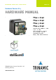
MECHATRONIC DRIVES WITH STEPPER MOTOR PANdrives Hardware Version V1.3 HARDWARE MANUAL + + PD42-1-1140 PD42-2-1140 PD42-3-1140 PD42-4-1140 Stepper Motor NEMA17 / 42mm 0.22 – 0.7 Nm with Controller / Driver up-to 2A RMS / 24V DC sensOstep™ encoder RS485, CAN, USB interfaces + TRINAMIC Motion Control GmbH & Co. KG Hamburg, Germany www.trinamic.
PD42-x-1140 Hardware Manual (V1.03 / 2018-JAN-25) Table of contents 1 2 3 4 Life support policy ....................................................................................................................................................... 3 Features ........................................................................................................................................................................... 4 Order codes .................................................................
PD42-x-1140 Hardware Manual (V1.03 / 2018-JAN-25) 1 Life support policy TRINAMIC Motion Control GmbH & Co. KG does not authorize or warrant any of its products for use in life support systems, without the specific written consent of TRINAMIC Motion Control GmbH & Co. KG. Life support systems are equipment intended to support or sustain life, and whose failure to perform, when properly used in accordance with instructions provided, can be reasonably expected to result in personal injury or death.
PD42-x-1140 Hardware Manual (V1.03 / 2018-JAN-25) 4 2 Features The PANdrive™ PD42-1-1140, PD42-2-1140, PD-3-1140 and PD42-4-1140 are small and compact full mechatronic solutions including NEMA17 / 42mm flange size stepper motors, the TMCM-1140 controller/ driver electronics and TRINAMIC sensOstep™ encoder for step-loss detection. The four PANdrives include stepper motor with different lengths and different holding torques (PD42-1-1140: 0.22Nm, PD42-2-1140: 0.36Nm, PD42-3-1140: 0.44Nm and PD42-4-1140: 0.
PD42-x-1140 Hardware Manual (V1.03 / 2018-JAN-25) 5 CANopen: CiA 301 + CiA 402 (homing mode, profile position mode and velocity mode) supported Fully supported by TMCL-IDE (PC based integrated development environment) Please see separate TMCL™ or CANopen firmware manual and for additional information TRINAMICS UNIQUE FEATURES – EASY TO USE WITH TMCL stallGuard2™ stallGuard2 is a high-precision sensorless load measurement using the back EMF on the coils.
PD42-x-1140 Hardware Manual (V1.03 / 2018-JAN-25) 6 3 Order codes The combination of motor and motor mounted controller/driver electronic is currently available with three stepper motors (different length and holding torque): The length of the PANdrives™ is specified without the length of the axis. For the overall length of the product please add 26 mm (see detailed drawings in chapter 3). Order code PD42-1-1140-option Description PANdrive with NEMA17 stepper motor, 0.
PD42-x-1140 Hardware Manual (V1.03 / 2018-JAN-25) 7 4 Mechanical and electrical interfacing All PD42-x-1140 consist of one out of four available NEMA17 / 42mm stepper motors with 2A RMS rated coil current with the same TMCM-1140 controller / driver electronics mounted on its backside and integrated sensOstep™ encoder. The PD42-1-1140 uses the QSH4218-34-20-022 stepper motor with 0.22Nm holding torque, the PD42-2-1140 uses the QSH4218-38-20-036 stepper motor with 0.
PD42-x-1140 Hardware Manual (V1.03 / 2018-JAN-25) 8 4.2 Stepper motor Main characteristics of the four different motors available as part of the PD42-x-1140 PANdrive™: Specifications Related PANdrive Step angle Step angle accuracy Ambient temperature Max. motor temperature Shaft radial play (450g load) Shaft axial play (450g load) Max radial force (20mm from front flange) Max axial force Rated voltage Rated phase current Phase resistance at 20°C Phase inductance (typ.
PD42-x-1140 Hardware Manual (V1.03 / 2018-JAN-25) 9 4.3 Integrated sensOstep™ encoder The PD42-x-1140 PANdrives offer integrated sensOstep™ encoders based on hall sensor technology. As the name “sensOstep™” already indicates intended use of this type of compact and highly integrated encoder is step loss detection of motor movements. As soon as the motor has been moved to a new location the position may be verified using this encoder feedback.
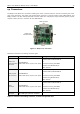
PD42-x-1140 Hardware Manual (V1.03 / 2018-JAN-25) 10 4.4 Connectors The PD42-x-1140 offers four connectors including the motor connector which is used for connecting the motor coils to the electronics. The power and communication connector is used for power supply, CAN interface, and RS485 interface. The 8pin multipurpose I/O connector offers four multipurpose inputs and two general purpose outputs. Further, there is a connector for the USB interface.
PD42-x-1140 Hardware Manual (V1.03 / 2018-JAN-25) 11 4.4.1 Power and Communication A 6pin 2mm pitch single row connector is used for power supply, RS485 and CAN serial communication. Note: CAN interface will be de-activated in case USB is connected due to internal sharing of hardware resources.
PD42-x-1140 Hardware Manual (V1.03 / 2018-JAN-25) 12 4.4.1.2 RS485 For remote control and communication with a host system the PD42-x-1140 provides a two wire RS485 bus interface. For proper operation the following items should be taken into account when setting up an RS485 network: 1. BUS STRUCTURE: The network topology should follow a bus structure as closely as possible. That is, the connection between each node and the bus itself should be as short as possible.
PD42-x-1140 Hardware Manual (V1.03 / 2018-JAN-25) 13 Slave Slave node n- 1 node n +5V pull-up (680R) RS485+ / RS485A termination resistor (220R) termination resistor (120R) RS485- / RS485B pull-down (680R) GND Figure 4.
PD42-x-1140 Hardware Manual (V1.03 / 2018-JAN-25) 14 2. BUS TERMINATION: Especially for longer busses and/or multiple nodes connected to the bus and/or high communication speeds, the bus should be properly terminated at both ends. The PD42-x-1140 does not integrate any termination resistor. Therefore, 120 Ohm termination resistors at both ends of the bus have to be added externally. 3.
PD42-x-1140 Hardware Manual (V1.03 / 2018-JAN-25) 15 4.4.2.1 Digital Inputs IN_1, IN_2, IN_3 The eight pin connector of the PD42-x-1140 provides three multipurpose digital inputs IN_1, IN_2 and IN_3. All three inputs accept up to +24V (nom.) input signals and offer the same input circuit with voltage resistor dividers, limiting diodes against over- and under-voltage and programmable 2k2 pull-up resistors. The pull-ups can be switched on or off for all three inputs at once in software.
PD42-x-1140 Hardware Manual (V1.03 / 2018-JAN-25) - - 16 All three digital inputs are connected to the on-board processor and can be used as general purpose digital inputs (default). In order to use IN_1 and IN_2 as STOP_L and STOP_R inputs, this function has to be enabled explicitly in software (factory default: switched off). With TMCL firmware the stop switch functionality can be enabled using SAP 12, 0, 0 (STOP_R / right limit switch) and SAP 13, 0, 0 (STOP_L / left limit switch).
PD42-x-1140 Hardware Manual (V1.03 / 2018-JAN-25) 17 VDD microcontroller GND Figure 4.8 General purpose output OUT_0 (simplified circuit) With TMCL firmware OUT_0 can be switched on (OUT_0 pulled low) using command SIO 0, 2, 1 and off again (OUT_0 floating) using command SIO 0, 2, 0 (this is also the factory default setting of this output). In case a floating output is not desired in the application an external resistor to e.g. supply voltage may be added.
PD42-x-1140 Hardware Manual (V1.03 / 2018-JAN-25) 18 4.4.3 Motor As motor connector a 4pin connector is available. The motor connector is used for connecting the four motor wires of the two motor coils of the bipolar stepper motor to the electronics. Do not connect or disconnect motor during operation! Motor cable and motor inductivity might lead to voltage spikes when the motor is disconnected / connected while energized.
PD42-x-1140 Hardware Manual (V1.03 / 2018-JAN-25) 19 USB BUS POWERED OPERATION MODE The PD42-x-1140 PANdrives™ support both, USB self powered operation (when an external power is supplied via the power supply connector) and USB bus powered operation, (no external power supply via power supply connector). On-board digital core logic will be powered via USB in case no other supply is connected (USB bus powered operation). The digital core logic includes the microcontroller itself and also the EEPROM.
PD42-x-1140 Hardware Manual (V1.03 / 2018-JAN-25) 20 5 Motor driver current The integrated stepper motor driver operates current controlled. The driver current may be programmed in software for motor coil currents up-to 2A RMS with 32 effective scaling steps in hardware (CS in table below). Explanation of different columns in table below: Motor current setting in software (TMCL) These are the values for TMCL axis parameter 6 (motor run current) and 7 (motor standby current).
PD42-x-1140 Hardware Manual (V1.03 / 2018-JAN-25) 21 Maximum current of the TMCM-1140 driver electronics has been selected in order to meet the max. / rated current of the stepper motor which is part of the PD42-x-1140 PANdrive. Nevertheless, please monitor motor temperature in application – especially when selecting high current settings for longer time without cooling the motor appropriately. Motor temperature should not rise above 80°C in application.
PD42-x-1140 Hardware Manual (V1.03 / 2018-JAN-25) 22 7 On-Board LEDs The PANdrive™ offers two LEDs in order to indicate status. The function of both LEDs is dependent on the firmware version. With standard TMCL firmware the green LED should be flashing slowly during operation and the red LED should be off. When there is no valid firmware programmed into the board or during firmware update the red and green LEDs are permanently on.
PD42-x-1140 Hardware Manual (V1.03 / 2018-JAN-25) 23 8 Operational ratings The operational ratings show the intended or the characteristic ranges and should be used as design values.
PD42-x-1140 Hardware Manual (V1.03 / 2018-JAN-25) 24 OPERATIONAL RATINGS OF CAN INTERFACE Symbol Parameter NCAN Number of nodes connected to single RS485 network fCAN Maximum bit rate supported on CAN connection Min Table 8.4 Operational ratings of the CAN interface Copyright © 2012-2018, TRINAMIC Motion Control GmbH & Co.
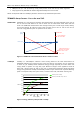
PD42-x-1140 Hardware Manual (V1.03 / 2018-JAN-25) 9 9.1.1 25 Torque Curves PD42-1-1140 Torque Curve PD42-1-1140 - 2A RMS Phase Current, 256 uSteps 0,30 torque[Nm] 0,25 0,20 0,15 0,10 0,05 0,00 10 100 1000 10000 speed[rpm] Figure 9.1 PD42-1-1140 torque vs. velocity 24V / 2A, 256µsteps 9.1.2 PD42-2-1140 Torque Curve PD42-2-1140 - 2A RMS Phase Current, 256 uSteps 0,45 0,40 torque[Nm] 0,35 0,30 0,25 0,20 0,15 0,10 0,05 0,00 10 100 1000 speed[rpm] Figure 9.2 PD42-2-1140 torque vs.
PD42-x-1140 Hardware Manual (V1.03 / 2018-JAN-25) 9.1.3 26 PD42-3-1140 Torque Curve PD42-3-1140 - 2A RMS Phase Current, 256 uSteps 0,60 torque[Nm] 0,50 0,40 0,30 0,20 0,10 0,00 10 100 1000 10000 speed[rpm] Figure 9.3 PD42-3-1140 torque vs. velocity 24V / 2A, 256µsteps 9.1.4 PD42-4-1140 Torque Curve PD42-4-1140 - 2A RMS Phase Current, 256 uSteps 0,80 0,70 torque[Nm] 0,60 0,50 0,40 0,30 0,20 0,10 0,00 10 100 1000 speed[rpm] Figure 9.4 PD42-4-1140 torque vs.
PD42-x-1140 Hardware Manual (V1.03 / 2018-JAN-25) 27 10 Functional description The PD42-x-1140 is a full mechatronic solution including a 42mm flange (NEMA17) bipolar stepper motor. It includes the controller / driver electronics TMCM-1140 and a choice between four different NEMA 17 / 42mm flange size bipolar hybrid stepper motors with different length and torque. The PD42-x-1140 can be controlled via USB, RS485 or CAN serial interfaces.
PD42-x-1140 Hardware Manual (V1.03 / 2018-JAN-25) 28 11 PD42-x-1140 Operational Description 11.1 Calculation: Velocity and Acceleration vs. Microstep and Fullstep Frequency The values of the parameters sent to the motion controller TMC429 integrated on the PD42-x-1140 PANdrive do not have typical motor values like rotations per second as velocity. But these values can be calculated from the TMC429 parameters as shown in this section.
PD42-x-1140 Hardware Manual (V1.03 / 2018-JAN-25) EXAMPLE Signal f_CLK velocity a_max pulse_div ramp_div usrs msf 16 MHz 1000 21 2048 32 122070.31 fsf [ Hz] a value 16 MHz 1000 1000 1 1 6 26 (16Mhz ) 2 1000 af 11 29 2 122070.31 Hz 1907.34Hz 119.21 MHz s MHz s 1.863 MHz 6 s 2 119.21 CALCULATION OF THE NUMBER OF ROTATIONS A stepper motor has e.g. 72 fullsteps per rotation. RPS RPM fsf 1907.34 26.49 fullsteps per rotation 72 fsf 60 1907.34 60 1589.
PD42-x-1140 Hardware Manual (V1.03 / 2018-JAN-25) 30 12 Revision history 12.1 Document revision Version 0.90 0.91 Date 2011-DEC-22 2012-MAY-02 Author GE GE 1.00 2012-JUN-26 SD 1.01 2012-JUL-30 SD 1.02 2013-MAR-26 SD 1.03 2018-JAN-25 GE Description Initial version Updated for TMCM-1140_V11 pcb version First complete version including the following chapters: Reset to factory defaults LEDs Torque curves Internal circuit of inputs corrected.
PD42-x-1140 Hardware Manual (V1.03 / 2018-JAN-25) Version Date 31 Description fault protection (up-to 70V fault protection) and supporting higher communication speeds (up-to 1Mbit/s). Conformal coating of both sides of the PCB. Provides improved protection against humidity and dust / swarf (e.g. in case of the motor mounted versions PD42-x-1140: tiny metal parts on the PCB attracted by the encoder magnet might lead to malfunction of the unprotected device). Table 12.