
User Manual

PD42-1140 CANopen® Firmware Manual • Firmware Version V3.20 | Document Revision V2.10 • 2018-DEC-01
35 / 109
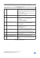
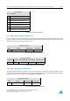
Bit Definitions
Bit Definition
0 Left limit switch deactivated if set.
1 Right limit switch deactivated if set.
2 Left limit switch inverted if set.
3 Right limit switch inverted if set.
4 Home switch deactivated if set.
5 Home switch inverted if set.
6 Shutdown input enabled if set.
Table 65: Bit Definitions (2005
h
)
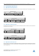
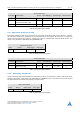
4.2.7 Object 200A
h
: Enable Drive Delay Time
This is an additional delay time (in milliseconds) between enabling the power stage and releasing the brake.
It can be used to prevent the brake from being released too early (before the hold current in the motor
has been reached). Please see also object 4.2.3.
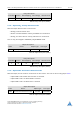
Object Description
Index Name Object Type Data Type
200A
h
Enable drive delay time Variable UNSIGNED16
Table 66: Object Description (200A
h
)
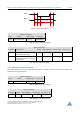
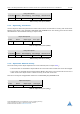
Entry Description
Sub-index Access PDO Mapping Value Range Default Value
0 rw no 0. . . 65535 0
Table 67: Entry Description (200A)
h
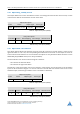
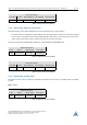
4.2.8 Object 200B
h
: Encoder Parameters
This object defines encoder parameters. These are the direction of rotation for external encoders (set to 1
if the direction is reversed compared to the motor) and if the position is to be intialized with the encoder
position. The object is only writable in SWITCHED_ON_DISABLED state.
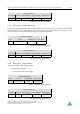
Object Description
Index Name Object Type Data Type
200B
h
Encoder parameters Array UNSIGNED8
Table 68: Object Description (200B
h
)
©2019 TRINAMIC Motion Control GmbH & Co. KG, Hamburg, Germany
Terms of delivery and rights to technical change reserved.
Download newest version at www.trinamic.com