PANDRIVE™ PANdrive™ for Stepper PD42-1140 CANopen® Firmware Manual Firmware Version V3.20 | Document Revision V2.10 • 2018-DEC-01 The PD42-1140 is a full mechatronic solution, made up of a TMCM-1140 stepper control module and a NEMA 17 (42mm flange size) motor. The PD42-1140 CANopen® firmware allows to control the module using the CANopen® protocol, making use of the Trinamic TMC429 motion controller and TMC262 motor driver.
/ 109 PD42-1140 CANopen® Firmware Manual • Firmware Version V3.20 | Document Revision V2.10 • 2018-DEC-01 Contents 1 2 3 4 Preface 1.1 General Features of this CANopen Implementation . . . . 1.2 Abbreviations used in this Manual . . . . . . . . . . . . . . . 1.3 Firmware Update . . . . . . . . . . . . . . . . . . . . . . . . . 1.4 Trinamic’s unique Features — easy to use with CANopen® 1.4.1 StallGuard2™ . . . . . . . . . . . . . . . . . . . . . . . 1.4.2 CoolStep™ . . . . . . . . . . . . . . . . . .
/ 109 PD42-1140 CANopen® Firmware Manual • Firmware Version V3.20 | Document Revision V2.10 • 2018-DEC-01 4.2.11 4.2.12 4.2.13 4.2.14 4.2.15 4.2.16 4.2.17 4.2.18 4.2.19 4.2.20 4.2.21 4.2.22 4.2.23 4.2.24 4.2.25 4.2.26 4.2.27 4.2.28 4.2.29 4.2.30 4.2.31 4.2.32 4.2.33 4.2.34 4.2.35 4.2.36 4.2.37 4.2.38 4.2.39 4.2.40 4.2.41 4.2.42 4.2.43 4.2.44 4.2.45 4.2.46 4.2.47 4.2.48 5 Object 2086h : Pulse Divisor . . . . . . . . . . . . Object 2087h : Maximum Velocity . . . . . . . . .
/ 109 PD42-1140 CANopen® Firmware Manual • Firmware Version V3.20 | Document Revision V2.10 • 2018-DEC-01 6 7 8 9 Profile Position Mode 6.1 Detailed Object Specifications . . . . . . . . . . . . . 6.1.1 Object 6040h : Control Word . . . . . . . . . . 6.1.2 Object 6041h : Status Word . . . . . . . . . . . 6.1.3 Object 6062h : Position Demand Value . . . . 6.1.4 Object 6063h : Position Actual Internal Value . 6.1.5 Object 6064h : Position Actual Value . . . . . . 6.1.
/ 109 PD42-1140 CANopen® Firmware Manual • Firmware Version V3.20 | Document Revision V2.10 • 2018-DEC-01 9.1.6 Homing Method 18: Homing on positive Limit Switch . . 9.1.7 Homing Method 19: Homing on positive Home Switch . 9.1.8 Homing Method 21: Homing on negative Home Switch . 9.1.9 Homing Method 33 and 34: Homing on next Index Pulse 9.1.10 Homing Method 35: Current Position as Home Position . 9.2 Detailed Object Specifications . . . . . . . . . . . . . . . . . . . . 9.2.1 Object 6040h : Control Word .
PD42-1140 CANopen® Firmware Manual • Firmware Version V3.20 | Document Revision V2.10 • 2018-DEC-01 1 6 / 109 Preface This document specifies objects and modes of operation of the Trinamic PD42-1140 stepper motor control module with CANopen firmware. The CANopen firmware is designed to fulfill the CANopen DS402 and DS301 standards. This manual assumes that the reader is already familiar with the basics of the CANopen protocol, defined by the DS301 and DS402 standards of the CAN-CiA.
PD42-1140 CANopen® Firmware Manual • Firmware Version V3.20 | Document Revision V2.10 • 2018-DEC-01 7 / 109 Further Characteristics • SYNC: consumer (TPDOs 3 are synchronous PDOs) • Emergency: producer • RTR: supported only for node guarding/life guarding • Heartbeat: consumer and producer 1.
PD42-1140 CANopen® Firmware Manual • Firmware Version V3.20 | Document Revision V2.10 • 2018-DEC-01 1.4 1.4.1 8 / 109 Trinamic’s unique Features — easy to use with CANopen® StallGuard2™ StallGuard2™ is a high-precision sensorless load measurement using the back EMF of the coils. It can be used for stall detection as well as other uses at loads below those which stall the motor. The StallGuard2™ measurement value changes linearly over a wide range of load, velocity, and current settings.
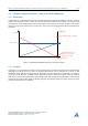
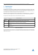
PD42-1140 CANopen® Firmware Manual • Firmware Version V3.20 | Document Revision V2.10 • 2018-DEC-01 0,9 Efficiency with coolStep 0,8 Efficiency with 50v torque reserve 0,7 0,6 0,5 Efficiency 0,4 0,3 0,2 0,1 0 0 50 100 150 200 250 300 350 Velocity [RPM] Figure 2: Energy Efficiency Example with CoolStep ©2019 TRINAMIC Motion Control GmbH & Co. KG, Hamburg, Germany Terms of delivery and rights to technical change reserved. Download newest version at www.trinamic.
PD42-1140 CANopen® Firmware Manual • Firmware Version V3.20 | Document Revision V2.10 • 2018-DEC-01 2 2.1 10 / 109 Communication Reference Model The application layer comprises a concept to configure and communicate real-time-data as well as the mechanisms for synchronization between devices. The functionality which the application layer offers to an application is logically divided over different service data objects (SDO) in the application layer.
PD42-1140 CANopen® Firmware Manual • Firmware Version V3.20 | Document Revision V2.10 • 2018-DEC-01 11 / 109 Service Types Type Definition Local service Involves only the local service object. The application issues a request to its local service object that executes the requested service without communicating with peer service object(s). Unconfirmed service Involves one or more peer service objects. The application issues a request to its local service object.
PD42-1140 CANopen® Firmware Manual • Firmware Version V3.20 | Document Revision V2.10 • 2018-DEC-01 2.2 12 / 109 NMT State Machine The finite state machine (FSM) or simply state machine is a model of behavior composed of a finite number of states, transitions between those states, and actions. It shows which way the logic runs when certain conditions are met. Starting and resetting the device is controlled via the state machine. The NMT state machine consists of the states shown in figure 3.
PD42-1140 CANopen® Firmware Manual • Firmware Version V3.20 | Document Revision V2.10 • 2018-DEC-01 13 / 109 CANopen device profile CiA DSP 402 Modes of operation: Profile Position (pp) Profile Velocity (pv) Homing (hm) ... Device control state machine CANopen Communication Profile CiA DS301 NMT State Machine CAN Figure 4: Communication Architecture 2.
PD42-1140 CANopen® Firmware Manual • Firmware Version V3.20 | Document Revision V2.10 • 2018-DEC-01 14 / 109 Application Communication Object dictionary State machine Application object Entry 1 Entry 2 Communication object Communication object Application object Communication object Application object Entry n Application object Communication object Bus system Process Figure 5: Device Model 2.4 Object Dictionary The most important part of a device profile is the object dictionary description.
PD42-1140 CANopen® Firmware Manual • Firmware Version V3.20 | Document Revision V2.10 • 2018-DEC-01 15 / 109 The communication profile area at indices 1000h through 1FFFh contains the communication specific parameters for the CAN network. These entries are common to all devices. The manufacturer segment at indices 2000h through 5FFFh contains manufacturer specific objects. These objects control the special features of the Trinamic PD42-1140 motion control device.
PD42-1140 CANopen® Firmware Manual • Firmware Version V3.20 | Document Revision V2.10 • 2018-DEC-01 3 16 / 109 Communication Area The communication area contains all objects that define the communication parameters of the CANopen device according to the DS301 standard. 3.1 Detailed Object Specifications 3.1.1 Object 1000h : Device Type This object contains information about the device type. The object 1000h describes the type of device and its functionality.
PD42-1140 CANopen® Firmware Manual • Firmware Version V3.20 | Document Revision V2.10 • 2018-DEC-01 17 / 109 Error Register Bits Bit Definition 0 Generic error 1 Current 2 Voltage 3 Temperature 4 Communication error 5 Device profile specific 6 Reserved (always 0) 7 Manufacturer specific Table 9: Error Register Bits 3.1.3 Object 1005h : COB-ID SYNC Message This object defines the COB-ID of the synchronization object (SYNC). Further, it defines whether the module generates the SYNC.
PD42-1140 CANopen® Firmware Manual • Firmware Version V3.20 | Document Revision V2.10 • 2018-DEC-01 3.1.4 Object 1008h : Manufacturer Device Name This object contains the name of the device as given by the manufacturer.
PD42-1140 CANopen® Firmware Manual • Firmware Version V3.20 | Document Revision V2.10 • 2018-DEC-01 19 / 109 Entry Description Sub-index Access PDO Mapping Value Range Default Value 0 ro no — Depends on device, e.g. 1.0. Table 18: Entry Description (100Ah ) 3.1.7 Object 100Ch : Guard Time The objects at index 100Ch and 100Dh shall indicate the configured guard time respectively the life time factor.
PD42-1140 CANopen® Firmware Manual • Firmware Version V3.20 | Document Revision V2.10 • 2018-DEC-01 20 / 109 There are several parameter groups: • Sub-index 0h : contains the largest sub-index that is supported. • Sub-index 1h : saves all parameters. • Sub-index 2h : saves communication parameters 2704h and 2705h . • Sub-index 3h : saves device profile parameters. • Sub-index 4h : saves motor 0 parameters.
PD42-1140 CANopen® Firmware Manual • Firmware Version V3.20 | Document Revision V2.10 • 2018-DEC-01 3.1.10 21 / 109 Object 1011h : Restore Parameters With this object the default values of parameters according to the communication or device profile are restored. By read access the device provides information about its capabilities to restore these values. There are several parameter groups: • Sub-index 0h : contains the largest sub-index that is supported.
PD42-1140 CANopen® Firmware Manual • Firmware Version V3.20 | Document Revision V2.10 • 2018-DEC-01 22 / 109 Entry Description Sub-index Description Access PDO Mapping Value Range Default Value 01h Restore all parameters rw no UNSIGNED32 — 02h Restore communication parameters rw no UNSIGNED32 — 03h Restore device profile parameters rw no UNSIGNED32 — 04h Restore motor axis 0 parameters rw no UNSIGNED32 — Table 28: Entry Description (1011h ) 3.1.
PD42-1140 CANopen® Firmware Manual • Firmware Version V3.20 | Document Revision V2.10 • 2018-DEC-01 3.1.13 23 / 109 Object 1016h : Consumer Heartbeat Time The consumer heartbeat time defines the expected heartbeat cycle time and thus has to be higher than the corresponding producer heartbeat time configured on the module producing this heartbeat. The monitoring starts after the reception of the first heartbeat. If the consumer heartbeat time is 0 the corresponding entry is not used.
/ 109 PD42-1140 CANopen® Firmware Manual • Firmware Version V3.20 | Document Revision V2.10 • 2018-DEC-01 Entry Description Sub-index Access PDO Mapping Value Range Default Value 0 rw no UNSIGNED16 0 Table 37: Entry Description (1017h ) 3.1.15 Object 1018h : Identity Object The object 1018h contains general information about the device: • The vendor ID (sub-index 01h ) contains a unique value allocated to each manufacturer. The vendor ID of Trinamic is 286h .
/ 109 PD42-1140 CANopen® Firmware Manual • Firmware Version V3.20 | Document Revision V2.10 • 2018-DEC-01 Entry Description Sub-index Description Access PDO Mapping Value Range Default Value 00h Number of entries ro no — 3 01h TMCL command rw no Octet string (7 bytes) — 02h Reply ro no UNSIGNED8 — 03h TMCL reply ro no Octet string (7 bytes) — Table 41: Entry Description (1023h ) 3.1.
PD42-1140 CANopen® Firmware Manual • Firmware Version V3.20 | Document Revision V2.10 • 2018-DEC-01 26 / 109 Sub-Index 02h contains the transmission type of the RPDO. This can be FFh or FEh for event-driven, or 00h for synchronous.
PD42-1140 CANopen® Firmware Manual • Firmware Version V3.20 | Document Revision V2.
PD42-1140 CANopen® Firmware Manual • Firmware Version V3.20 | Document Revision V2.10 • 2018-DEC-01 28 / 109 definition, set this bit to inactivate the PDO. Sub-index 02h contains the transmission type of the RPDO. This can be FFh or FEh for event-driven, or 00h or 01h for synchronous. Sub-index 03h contains the inhibit time, given in milliseconds. After a TPDO has been sent, it will not be sent again before the inhibit time has elapsed. Sub-index 04h is not used.
PD42-1140 CANopen® Firmware Manual • Firmware Version V3.20 | Document Revision V2.10 • 2018-DEC-01 3.1.21 29 / 109 Objects 1A00h – 1A03h : Transmit PDO Mapping Parameter These objects contain the mapping parameters for the TPDOs the device is able to transmit. The sub-index 00h contains the number of valid entries within the mapping record. This number of entries is also the number of the application variables which shall be transmitted with the corresponding TPDO.
/ 109 PD42-1140 CANopen® Firmware Manual • Firmware Version V3.20 | Document Revision V2.10 • 2018-DEC-01 4 Manufacturer specific Area The manufacturer segment contains manufacturer specific objects. These objects control the special features of the Trinamic Motion Control device PD42-1140. 4.1 Objects related to CoolStep™ Figure 6 shows an overview of the CoolStep™ related objects for motor #0. Please bear in mind that the figure only shows one example for a drive.
PD42-1140 CANopen® Firmware Manual • Firmware Version V3.20 | Document Revision V2.10 • 2018-DEC-01 31 / 109 CoolStep Adjustment Objects Object Name Description 2003h Absolute maximum current The maximum value is 255. This value means 100% of the maximum current of the module. The current adjustment is within the range 0. . . 255 and can be adjusted in 32 steps (0. . . 255 divided by eight; step 0 = 0. . . 7, step 1 = 8. . . 15 and so on).
PD42-1140 CANopen® Firmware Manual • Firmware Version V3.20 | Document Revision V2.10 • 2018-DEC-01 4.2 Detailed Object Specifications 4.2.1 Object 2000h : Microstep Resolution 32 / 109 This object sets the microstep resolution of the drive. A value of 8 selects 256 (28 ) microsteps per full step.
/ 109 PD42-1140 CANopen® Firmware Manual • Firmware Version V3.20 | Document Revision V2.
PD42-1140 CANopen® Firmware Manual • Firmware Version V3.20 | Document Revision V2.10 • 2018-DEC-01 4.2.5 34 / 109 Object 2004h : Standby Current This object defines the current used when the motor is standing (two seconds after the last move). A value of 255 means 100% of the maximum current of the drive.
PD42-1140 CANopen® Firmware Manual • Firmware Version V3.20 | Document Revision V2.10 • 2018-DEC-01 35 / 109 Bit Definitions Bit Definition 0 Left limit switch deactivated if set. 1 Right limit switch deactivated if set. 2 Left limit switch inverted if set. 3 Right limit switch inverted if set. 4 Home switch deactivated if set. 5 Home switch inverted if set. 6 Shutdown input enabled if set. Table 65: Bit Definitions (2005h ) 4.2.
/ 109 PD42-1140 CANopen® Firmware Manual • Firmware Version V3.20 | Document Revision V2.10 • 2018-DEC-01 Entry Description Sub-index Description Access PDO Mapping Value Range Default Value 1 Not used rw no — — 2 Direction of rotation (external encoders only) rw no 0/1 0 3 Initialize position rw no 0/1 1 Table 69: Entry Description (200Bh ) 4.2.9 Object 200Ch : Brake Current Feed This object configures how much current has to be fed into the brake to apply and to release it.
PD42-1140 CANopen® Firmware Manual • Firmware Version V3.20 | Document Revision V2.10 • 2018-DEC-01 37 / 109 Entry Description Sub-index Access PDO Mapping Value Range Default Value 0 rw no 0. . . 13 0 Table 73: Entry Description (2085h ) 4.2.11 Object 2086h : Pulse Divisor Use this object to define the pulse divisor when internal units are selected for velocity and acceleration. Writing to this object is only possible in SWITCHED_ON_DISABLED state.
PD42-1140 CANopen® Firmware Manual • Firmware Version V3.20 | Document Revision V2.10 • 2018-DEC-01 38 / 109 Entry Description Sub-index Access PDO Mapping Value Range Default Value 0 rw no 0. . . 2047 0 Table 77: Entry Description (2087h ) 4.2.13 Object 2088h : Maximum Acceleration The functionality of this object depends on the unit selection (refer to object 208Eh ). • If internal units are selected this object will be set to the fixed value of 2047 and cannot be changed.
PD42-1140 CANopen® Firmware Manual • Firmware Version V3.20 | Document Revision V2.10 • 2018-DEC-01 39 / 109 Entry Description Sub-index Access PDO Mapping Value Range Default Value 0 rw no 0. . . 65535 0 Table 81: Entry Description (2089h ) 4.2.15 Object 208Ch : Velocity Dimension Index With this object different units can be chosen: • Writing 0 selects internal units. • Writint 164 selects RPM for velocity and RPM/s for acceleration.
PD42-1140 CANopen® Firmware Manual • Firmware Version V3.20 | Document Revision V2.10 • 2018-DEC-01 40 / 109 Entry Description Sub-index Access PDO Mapping Value Range Default Value 0 ro no 0/177/179 0 Table 85: Entry Description (208Eh ) 4.2.17 Object 2092h : Chopper Blank Time This object serves for selecting the comparator blank time. This time needs to safely cover the switching event and the duration of the ringing on the sense resistor.
PD42-1140 CANopen® Firmware Manual • Firmware Version V3.20 | Document Revision V2.10 • 2018-DEC-01 4.2.19 41 / 109 Object 2094h : Chopper Hysteresis Decrement This object serves for the hysteresis decrement setting. This setting determines the slope of the hysteresis during on time and during fast decay time.
PD42-1140 CANopen® Firmware Manual • Firmware Version V3.20 | Document Revision V2.10 • 2018-DEC-01 4.2.21 42 / 109 Object 2096h : Chopper Hysteresis Start This object provides the hysteresis start setting. Please notice that this value is an offset to the hysteresis end value.
PD42-1140 CANopen® Firmware Manual • Firmware Version V3.20 | Document Revision V2.10 • 2018-DEC-01 43 / 109 Object Description Index Name Object Type Data Type 2098h Smart Energy Current Minimum Variable UNSIGNED8 Table 98: Object Description (2098h ) Entry Description Sub-index Access PDO Mapping Value Range Default Value 0 rw no 0/1 0 Table 99: Entry Description (2098h ) 4.2.
PD42-1140 CANopen® Firmware Manual • Firmware Version V3.20 | Document Revision V2.10 • 2018-DEC-01 44 / 109 Object Description Index Name Object Type Data Type 209Ah Smart Energy Hysteresis Variable UNSIGNED8 Table 102: Object Description (209Ah ) Entry Description Sub-index Access PDO Mapping Value Range Default Value 0 rw no 0. . . 15 0 Table 103: Entry Description (209Ah ) 4.2.26 Object 209Bh : Smart Energy Current Up Step This object sets the current increment step.
PD42-1140 CANopen® Firmware Manual • Firmware Version V3.20 | Document Revision V2.10 • 2018-DEC-01 45 / 109 Object Description Index Name Object Type Data Type 209Ch Smart Energy Hysteresis Start Variable UNSIGNED8 Table 106: Object Description (209Ch ) Entry Description Sub-index Access PDO Mapping Value Range Default Value 0 rw no 0. . . 15 0 Table 107: Entry Description (209Ch ) 4.2.
PD42-1140 CANopen® Firmware Manual • Firmware Version V3.20 | Document Revision V2.10 • 2018-DEC-01 46 / 109 Object Description Index Name Object Type Data Type 209Eh StallGuard2 Threshold Variable SIGNED8 Table 110: Object Description (209Eh ) Entry Description Sub-index Access PDO Mapping Value Range Default Value 0 rw no -63. . . 63 0 Table 111: Entry Description (209Eh ) 4.2.
PD42-1140 CANopen® Firmware Manual • Firmware Version V3.20 | Document Revision V2.10 • 2018-DEC-01 47 / 109 Entry Description Sub-index Access PDO Mapping Value Range Default Value 0 rw no 0. . . 2147483647 0 Table 115: Entry Description (20A4h ) 4.2.32 Object 20A5h : Smart Energy Threshold Speed The CoolStep™ functionality will be enabled when the actual speed is above this speed. It will be disabled again when the actual speed drops below this value.
PD42-1140 CANopen® Firmware Manual • Firmware Version V3.20 | Document Revision V2.10 • 2018-DEC-01 Object Description Index Name Object Type Data Type 2101h Actual Load Value Variable UNSIGNED16 Table 120: Object Description (2101h ) Entry Description Sub-index Access PDO Mapping Value Range Default Value 0 ro no 0. . . 1023 0 Table 121: Entry Description (2101h ) 4.2.35 Object 2102h : Driver Error Flags This object shows the error flags of the motor driver IC.
PD42-1140 CANopen® Firmware Manual • Firmware Version V3.20 | Document Revision V2.10 • 2018-DEC-01 49 / 109 Entry Description Sub-index Access PDO Mapping Value Range Default Value 0 ro no 0. . . 255 0 Table 124: Entry Description (2102h ) 4.2.36 Object 2107h : Microstep Resolution Display This object shows the microstep resolution, set by object 2000h (please see section 4.2.1).
PD42-1140 CANopen® Firmware Manual • Firmware Version V3.20 | Document Revision V2.10 • 2018-DEC-01 4.2.38 50 / 109 Object 2700h : TMCL Direct Communication After writing the make signature 656b616dh to this object the drive switches to TMCL mode. The drive can then only be controlled via TMCL commands written to the OS command object 1023/01h . The drive can only be reset to normal CANopen functionality using the DS-301 reset application command.
PD42-1140 CANopen® Firmware Manual • Firmware Version V3.20 | Document Revision V2.10 • 2018-DEC-01 4.2.40 51 / 109 Object 2702h : Device Digital Inputs Bits 23. . . 16 of this object reflect the states of the general purpose inputs of the module. The number of available inputs depends on the module type.
PD42-1140 CANopen® Firmware Manual • Firmware Version V3.20 | Document Revision V2.
PD42-1140 CANopen® Firmware Manual • Firmware Version V3.20 | Document Revision V2.10 • 2018-DEC-01 4.2.43 53 / 109 Object 2705h : Node ID On modules that do not have address switches the node ID can be selected using this object. On modules with address switches the node ID is normally selected using the address switches. Only when the address switches are set to an invalid value (0 or >127) this object overrides the address switch setting.
PD42-1140 CANopen® Firmware Manual • Firmware Version V3.20 | Document Revision V2.10 • 2018-DEC-01 4.2.45 Object 2707h : CAN Bit Rate Load This object shows the selected CAN bit rate. Object Description Index Name Object Type Data Type 2707h CAN Bit Rate Load Variable UNSIGNED8 Table 145: Object Description (2707h ) Entry Description Sub-index Access PDO Mapping Value Range Default Value 0 ro no 20. . . 1000 depends on bit rate Table 146: Entry Description (2707)h 4.2.
PD42-1140 CANopen® Firmware Manual • Firmware Version V3.20 | Document Revision V2.10 • 2018-DEC-01 Entry Description Sub-index Description Access PDO Mapping Value Range Default Value 1 Analog input 0 ro yes 0. . . 4095 – Table 150: Entry Description (270Eh ) 4.2.48 Object 2710h : Pull-up Resistors This object enables or disables the built-in pull-up resistors for the digital inputs. Value Definition Value Description 0 All pull-up resistors off. 1 All pull-up resistors on.
PD42-1140 CANopen® Firmware Manual • Firmware Version V3.20 | Document Revision V2.10 • 2018-DEC-01 5 56 / 109 Profile specific Area The profile segment contains CiA-402 standard motion control objects. These objects control the motion control functions of the PD42-1140. Since it is not possible to operate the modes in parallel, the user is able to activate the required function by selecting a mode of operation.
PD42-1140 CANopen® Firmware Manual • Firmware Version V3.20 | Document Revision V2.10 • 2018-DEC-01 5.1.2 57 / 109 Object 605Bh : Shutdown Option Code This object indicates what action is performed if there is a transition from operation enabled state to ready to switch on state. The shutdown option code always has the value 0 as only this is supported.
PD42-1140 CANopen® Firmware Manual • Firmware Version V3.20 | Document Revision V2.10 • 2018-DEC-01 58 / 109 Entry Description Sub-index Access PDO Mapping Value Range Default Value 0 rw no 1 1 Table 162: Entry Description (605Ch ) 5.1.4 Object 605Dh : Halt Option Code This object indicates what action is performed when the halt function is executed. The slow down ramp is the deceleration value of the used mode of operation.
PD42-1140 CANopen® Firmware Manual • Firmware Version V3.20 | Document Revision V2.10 • 2018-DEC-01 59 / 109 Object Description Index Name Object Type Data Type 605Eh Fault reaction option code Variable UNSIGNED16 Table 167: Object Description (605Eh ) Entry Description Sub-index Access PDO Mapping Value Range Default Value 0 rw no 2 2 Table 168: Entry Description (605Eh ) 5.1.6 Object 6060h : Modes of Operation This object indicates the requested operation mode.
PD42-1140 CANopen® Firmware Manual • Firmware Version V3.20 | Document Revision V2.10 • 2018-DEC-01 Note 60 / 109 It is not allowed to write the same mode number twice to object 6060h . So before writing a new value to object 6060h , either check object 6061h or object 6060h to see if the operating mode has not already been set to that value. 5.1.7 Object 6061h : Modes of Operation Display This object shows the operating mode that is currently set.
PD42-1140 CANopen® Firmware Manual • Firmware Version V3.20 | Document Revision V2.10 • 2018-DEC-01 61 / 109 Value Definition Value Mode 0 Encoder used -1 No encoder Table 175: Value Description (606Ah ) Object Description Index Name Object Type Data Type 606Ah Sensor selection code Variable SIGNED16 Table 176: Object Description (606Ah ) Entry Description Sub-index Access PDO Mapping Value Range Default Value 0 rw no 0/-1 -1 Table 177: Entry Description (606Ah ) 5.1.
PD42-1140 CANopen® Firmware Manual • Firmware Version V3.20 | Document Revision V2.
PD42-1140 CANopen® Firmware Manual • Firmware Version V3.20 | Document Revision V2.10 • 2018-DEC-01 6 63 / 109 Profile Position Mode A target position is applied to the trajectory generator. It is generating a position demand value for the position control loop described in the position control function. Please refer to object 6060h (section 5.1.6) for information about how to choose an operation mode. Object 6061h (section 5.1.7) shows the operation mode that is set. 6.
PD42-1140 CANopen® Firmware Manual • Firmware Version V3.20 | Document Revision V2.10 • 2018-DEC-01 6.1.1 64 / 109 Object 6040h : Control Word This object indicates the received command controlling the power drive system finite state automaton (PDS FSA). The CiA-402 state machine can be controlled using this object. Please refer to figure 8 for detailed information.
PD42-1140 CANopen® Firmware Manual • Firmware Version V3.20 | Document Revision V2.10 • 2018-DEC-01 65 / 109 Object Description Index Name Object Type Data Type 6040h Controlword Variable UNSIGNED16 Table 186: Object Description (6040h in pp Mode) Entry Description Sub-index Access PDO Mapping Value Range Default Value 0 rw see CiA402-3 See command coding above. Table 187: Entry Description (6040h in pp Mode) 6.1.
PD42-1140 CANopen® Firmware Manual • Firmware Version V3.20 | Document Revision V2.10 • 2018-DEC-01 66 / 109 Operation Mode specific Bits in pp Mode Bit Name Definition 10 Target reached Set when the motor is within the position window. 12 Set point acknowledged 0: Set point processed. 1: Set point still in process. 13 Following error Not supported.
PD42-1140 CANopen® Firmware Manual • Firmware Version V3.20 | Document Revision V2.10 • 2018-DEC-01 67 / 109 Object Description Index Name Object Type Data Type 6062h Position Demand Value Variable SIGNED32 Table 194: Object Description (6062h ) Entry Description Sub-index Access PDO Mapping Value Range Default Value 0 ro Refer to CiA402-3 SIGNED32 no Table 195: Entry Description (6062h ) 6.1.
PD42-1140 CANopen® Firmware Manual • Firmware Version V3.20 | Document Revision V2.10 • 2018-DEC-01 68 / 109 Entry Description Sub-index Access PDO Mapping Value Range Default Value 0 ro Refer to CiA402-3 SIGNED32 no Table 199: Entry Description (6064h ) 6.1.6 Object 6065h : Following Error Window This object indicates the configured range of tolerated position values symmetrically to the position demand value.
PD42-1140 CANopen® Firmware Manual • Firmware Version V3.20 | Document Revision V2.10 • 2018-DEC-01 69 / 109 Object Description Index Name Object Type Data Type 6067h Position Window Variable UNSIGNED32 Table 202: Object Description (6067h ) Entry Description Sub-index Access PDO Mapping Value Range Default Value 0 rw no UNSIGNED32 FFFFFFFFh Table 203: Entry Description (6067h ) 6.1.
PD42-1140 CANopen® Firmware Manual • Firmware Version V3.20 | Document Revision V2.10 • 2018-DEC-01 70 / 109 Entry Description Sub-index Access PDO Mapping Value Range Default Value 0 ro Refer to CiA402-3 SIGNED32 no Table 207: Entry Description (606Ch ) 6.1.
PD42-1140 CANopen® Firmware Manual • Firmware Version V3.20 | Document Revision V2.10 • 2018-DEC-01 71 / 109 Entry Description Sub-index Description Access PDO Mapping Value Range Default Value 1 Mininmum Position Limit rw no SIGNED32 -2147483648 2 Maximum Position Limit rw no SIGNED32 2147483647 Table 211: Entry Description (607Dh ) 6.1.
PD42-1140 CANopen® Firmware Manual • Firmware Version V3.20 | Document Revision V2.10 • 2018-DEC-01 6.1.14 72 / 109 Object 6083h : Profile Acceleration This object indicates the configured acceleration. Object 6083h sets the maximum acceleration to be used in profile position and profile velocity mode. The units for object 6083h can be choosen with object 208Eh , described in section 4.2.16.
PD42-1140 CANopen® Firmware Manual • Firmware Version V3.20 | Document Revision V2.10 • 2018-DEC-01 73 / 109 Object Description Index Name Object Type Data Type 6085h Quick stop deceleration Variable UNSIGNED32 Table 220: Object Description (6085h ) Entry Description Sub-index Access PDO Mapping Value Range Default Value 0 rw no UNSIGNED32 51200 Table 221: Entry Description (6085h ) 6.
PD42-1140 CANopen® Firmware Manual • Firmware Version V3.20 | Document Revision V2.10 • 2018-DEC-01 7 74 / 109 Velocity Mode The velocity mode is used to control the velocity of the drive without a special regard of the position. It contains limit functions. The input parameters in velocity mode include: • Velocity • Acceleration • Deceleration • Quick stop deceleration Note 7.1 7.1.1 Compared to the profile velocity (pv) mode, the vl mode offers only a very limited functionality.
PD42-1140 CANopen® Firmware Manual • Firmware Version V3.20 | Document Revision V2.
PD42-1140 CANopen® Firmware Manual • Firmware Version V3.20 | Document Revision V2.10 • 2018-DEC-01 Trinamic Specific Bits Bit Name Definition 14 Motor activity 0: Motor stands still. 1: Motor rotates. 15 Direction of rotation This bit shows the direction of rotation. Table 227: Trinamic Specific Bits Operation Mode specific Bits in vl Mode Bit Name Definition 10 Target reached Indicates that the target speed has been reached. 12 Speed Not supported. 13 Max. slippage error Not supported.
PD42-1140 CANopen® Firmware Manual • Firmware Version V3.20 | Document Revision V2.10 • 2018-DEC-01 77 / 109 Entry Description Sub-index Access PDO Mapping Value Range Default Value 0 rw see CiA402-3 See state coding above Table 231: Entry Description (6041h in vl Mode) 7.1.3 Object 6042h : vl Target Velocity This object indicates the required target velocity when the velocity mode is active. Use this object to control the velocity of the motor in velocity mode.
/ 109 PD42-1140 CANopen® Firmware Manual • Firmware Version V3.20 | Document Revision V2.10 • 2018-DEC-01 7.1.5 Object 6044h : vl Velocity Actual Value This object shows the actual velocity of the motor when the motor is in velocity mode. The value is given in the same units as vl target velocity and vl velocity demand (which depends on the setting of object 208Ch ).
/ 109 PD42-1140 CANopen® Firmware Manual • Firmware Version V3.20 | Document Revision V2.
PD42-1140 CANopen® Firmware Manual • Firmware Version V3.20 | Document Revision V2.10 • 2018-DEC-01 80 / 109 • Write 15 to object 6040h to switch to OPERATION_ENABLED state. • Write the desired target speed (e.g. 500) to object 6042h . The motor now accelerates to that speed. • Stop the motor by writing 0 to object 6042h . ©2019 TRINAMIC Motion Control GmbH & Co. KG, Hamburg, Germany Terms of delivery and rights to technical change reserved. Download newest version at www.trinamic.
PD42-1140 CANopen® Firmware Manual • Firmware Version V3.20 | Document Revision V2.10 • 2018-DEC-01 8 81 / 109 Profile Velocity Mode The profile velocity mode is used to control the velocity of the drive without a special regard of the position. It contains limit functions and trajectory generation. The profile velocity mode covers the following sub-functions: • Demand value input via trajectory generator. • Monitoring of the profile velocity using a window-function.
PD42-1140 CANopen® Firmware Manual • Firmware Version V3.20 | Document Revision V2.
PD42-1140 CANopen® Firmware Manual • Firmware Version V3.20 | Document Revision V2.10 • 2018-DEC-01 Trinamic Specific Bits Bit Name Definition 14 Motor activity 0: Motor stands still. 1: Motor rotates. 15 Direction of rotation This bit shows the direction of rotation. Table 249: Trinamic Specific Bits Operation Mode specific Bits in pv Mode Bit Name Definition 10 Target reached Indicates that the target speed has been reached. 12 Speed Not supported. 13 Max. slippage error Not supported.
PD42-1140 CANopen® Firmware Manual • Firmware Version V3.20 | Document Revision V2.10 • 2018-DEC-01 84 / 109 Entry Description Sub-index Access PDO Mapping Value Range Default Value 0 rw see CiA402-3 See state coding above Table 253: Entry Description (6041h in pv Mode) 8.1.3 Object 6062h : Position Demand Value This object provides the demanded position value. The value is given in microsteps. Object 6062h indicates the actual position that the motor should have.
PD42-1140 CANopen® Firmware Manual • Firmware Version V3.20 | Document Revision V2.10 • 2018-DEC-01 85 / 109 Object Description Index Name Object Type Data Type 6064h Position Actual Value Variable SIGNED32 Table 258: Object Description (6064h ) Entry Description Sub-index Access PDO Mapping Value Range Default Value 0 ro Refer to CiA402-3 SIGNED32 no Table 259: Entry Description (6064h ) 8.1.
PD42-1140 CANopen® Firmware Manual • Firmware Version V3.20 | Document Revision V2.10 • 2018-DEC-01 86 / 109 Object Description Index Name Object Type Data Type 606Ch Velocity Actual Value Variable SIGNED32 Table 262: Object Description (606Ch ) Entry Description Sub-index Access PDO Mapping Value Range Default Value 0 ro Refer to CiA402-3 SIGNED32 no Table 263: Entry Description (606Ch ) 8.1.
PD42-1140 CANopen® Firmware Manual • Firmware Version V3.20 | Document Revision V2.10 • 2018-DEC-01 87 / 109 In profile velocity mode, this object also sets the deceleration to be used (the deceleration ramp is always the same as the acceleration ramp in pv mode).
PD42-1140 CANopen® Firmware Manual • Firmware Version V3.20 | Document Revision V2.10 • 2018-DEC-01 88 / 109 Entry Description Sub-index Access PDO Mapping Value Range Default Value 0 rw see CiA402-3 SIGNED32 0 Table 271: Entry Description (60FFh ) 8.2 How to move a Motor in pv Mode Here is a little example that shows how to get a motor running in pv mode.
PD42-1140 CANopen® Firmware Manual • Firmware Version V3.20 | Document Revision V2.10 • 2018-DEC-01 9 89 / 109 Homing Mode This chapter describes the method by which a drive seeks the home position (reference point). There are various methods of achieving this using limit switches at the ends of travel or a home switch in mid-travel. Some methods also use the index (zero) pulse train from an incremental encoder. The user may specify the speeds, acceleration and the method of homing.
PD42-1140 CANopen® Firmware Manual • Firmware Version V3.20 | Document Revision V2.10 • 2018-DEC-01 9.1 90 / 109 Homing Methods The PD42-1140 supports a subset of different standard CANopen homing methods. The homing method that is to be used can be choosen via object 6098h (section 9.2.5). Supported Homing Methods Method Description 0 No homing (default value for object 6098h ). 1 Search the left end switch, then search the next encoder index pulse.
PD42-1140 CANopen® Firmware Manual • Firmware Version V3.20 | Document Revision V2.10 • 2018-DEC-01 9.1.2 91 / 109 Homing Method 2: Homing on positive Limit Switch and Index Pulse Using this method, the initial direction of movement shall be rightward if the positive limit switch is inactive (here: low). The position of home shall be at the first index pulse to the left of the position where the positive limit switch becomes inactive. 2 2 Index pulse Positive limit switch Figure 11: Homing Method 2 9.
PD42-1140 CANopen® Firmware Manual • Firmware Version V3.20 | Document Revision V2.10 • 2018-DEC-01 92 / 109 5 5 Index pulse Home switch Figure 13: Homing Method 5 9.1.5 Homing Method 17: Homing on negative Limit Switch Using this method, the initial direction of movement shall be leftward if the negative limit switch is inactive (here: low). The home position shall at the point where the negative limit switch becomes inactive. 17 17 Negative limit switch Figure 14: Homing Method 17 9.1.
PD42-1140 CANopen® Firmware Manual • Firmware Version V3.20 | Document Revision V2.10 • 2018-DEC-01 9.1.7 93 / 109 Homing Method 19: Homing on positive Home Switch Using this method, the initial direction of movement shall be dependent on the state of the home switch. The home position shall be at the point where the home switch changes state. If the initial direction of movement leads away from the home switch, the drive shall reverse on encountering the relevant limit switch.
PD42-1140 CANopen® Firmware Manual • Firmware Version V3.20 | Document Revision V2.10 • 2018-DEC-01 94 / 109 33 34 Index pulse Figure 18: Homing Methods 33 and 34 9.1.10 Homing Method 35: Current Position as Home Position In this method, the current position shall be taken to be the home position. This method does not require the drive device to be in operation enabled state. ©2019 TRINAMIC Motion Control GmbH & Co. KG, Hamburg, Germany Terms of delivery and rights to technical change reserved.
PD42-1140 CANopen® Firmware Manual • Firmware Version V3.20 | Document Revision V2.10 • 2018-DEC-01 9.2 9.2.1 95 / 109 Detailed Object Specifications Object 6040h : Control Word This object indicates the received command controlling the power drive system finite state automaton (PDS FSA). The CiA-402 state machine can be controlled using this object. Please refer to figure 8 for detailed information.
PD42-1140 CANopen® Firmware Manual • Firmware Version V3.20 | Document Revision V2.10 • 2018-DEC-01 96 / 109 Object Description Index Name Object Type Data Type 6040h Controlword Variable UNSIGNED16 Table 276: Object Description (6040h in hm Mode) Entry Description Sub-index Access PDO Mapping Value Range Default Value 0 rw see CiA402-3 See command coding above. Table 277: Entry Description (6040h in hm Mode) 9.2.
PD42-1140 CANopen® Firmware Manual • Firmware Version V3.20 | Document Revision V2.10 • 2018-DEC-01 97 / 109 Operation Mode specific Bits in hm Mode Bit Name Definition 10 Target reached Set when the zero position has been found or homing has been stopped by setting controlword bit 4 to zero. 12 Home attained Set when zero position has been found. 13 Homing error Not supported.
PD42-1140 CANopen® Firmware Manual • Firmware Version V3.20 | Document Revision V2.10 • 2018-DEC-01 98 / 109 Object Description Index Name Object Type Data Type 606Ch Velocity Actual Value Variable SIGNED32 Table 284: Object Description (606Ch ) Entry Description Sub-index Access PDO Mapping Value Range Default Value 0 ro Refer to CiA402-3 SIGNED32 no Table 285: Entry Description (606Ch ) 9.2.
/ 109 PD42-1140 CANopen® Firmware Manual • Firmware Version V3.20 | Document Revision V2.10 • 2018-DEC-01 9.2.5 Object 6098h : Homing Method The homing method to be used can be selected by writing to this object. Please see table 272 for a list of homing methods supported by the current version of the PD42-1140 CANopen firmware.
PD42-1140 CANopen® Firmware Manual • Firmware Version V3.20 | Document Revision V2.10 • 2018-DEC-01 100 / 109 Object Description Index Name Object Type Data Type 609Ah Homing acceleration Variable UNSIGNED32 Table 292: Object Description (609Ah ) Entry Description Sub-index Access PDO Mapping Value Range Default Value 0 rw no UNSIGNED32 0 Table 293: Entry Description (609Ah ) 9.3 How to start a Homing in hm Mode Here is a little example that shows how to home the motor in hm mode.
PD42-1140 CANopen® Firmware Manual • Firmware Version V3.20 | Document Revision V2.10 • 2018-DEC-01 10 101 / 109 Emergency Messages (EMCY) The module sends an emergency message if an error occurs. The message contains information about the error type. The module can map internal errors and object 1001h (error register) is part of every emergency object.
PD42-1140 CANopen® Firmware Manual • Firmware Version V3.20 | Document Revision V2.10 • 2018-DEC-01 Error code Additional byte 102 / 109 Description 1 2 3 4 5 8110h 1 255 0 0 0 CAN controller overflow The receive message buffer of the CAN controller hardware is full and some CAN messages are lost. 8110h 2 255 0 0 0 CAN Tx buffer overflow The software CAN transmit buffer is full and thus some CAN messages are lost.
/ 109 PD42-1140 CANopen® Firmware Manual • Firmware Version V3.20 | Document Revision V2.10 • 2018-DEC-01 11 1 2 3 4 5 6 7 8 9 Figures Index stallGuard2 Load Measurement as a Function of Load . . . . . . . . . . . . . Energy Efficiency Example with CoolStep NMT State Machine . . . . . . . . . . . . Communication Architecture . . . . . . Device Model . . . . . . . . . . . . . . . CoolStep Adjustment Points and Thresholds . . . . . . . . . . . . . . . . . Brake Output Timing . . . . . . . . . . .
/ 109 PD42-1140 CANopen® Firmware Manual • Firmware Version V3.20 | Document Revision V2.10 • 2018-DEC-01 12 1 2 3 4 5 6 7 8 9 10 11 12 13 14 15 16 17 18 19 20 21 22 23 24 25 26 27 28 29 30 31 32 33 34 35 36 37 38 39 40 41 42 43 44 45 46 47 48 49 50 51 52 Tables Index Abbreviations used in this Manual Service Primitives . . . . . . . . . . Service Types . . . . . . . . . . . . Object Dictionary . . . . . . . . . . Object Description (1000h ) . . . . . Entry Description (1000h ) . . . . .
PD42-1140 CANopen® Firmware Manual • Firmware Version V3.20 | Document Revision V2.10 • 2018-DEC-01 105 106 107 108 109 110 111 112 113 114 115 116 117 118 119 120 121 122 123 124 125 126 127 128 129 130 131 132 133 134 135 136 137 138 139 140 141 142 143 144 145 146 147 148 149 150 151 152 153 154 155 156 157 158 Entry Description (209Bh ) . Object Description (209Ch ) . Entry Description (209Ch ) . Object Description (209Dh ) Entry Description (209Dh ) . Object Description (209Eh ) .
PD42-1140 CANopen® Firmware Manual • Firmware Version V3.20 | Document Revision V2.10 • 2018-DEC-01 212 213 214 215 216 217 218 219 220 221 222 223 224 225 226 227 228 229 230 231 232 233 234 235 236 237 238 239 240 241 242 243 244 245 246 247 248 249 250 251 252 253 254 255 Object Description (6081h ) . . . . . . . Entry Description (6081h ) . . . . . . . Object Description (6082h ) . . . . . . . Entry Description (6082h ) . . . . . . . Object Description (6083h ) . . . . . . .
PD42-1140 CANopen® Firmware Manual • Firmware Version V3.20 | Document Revision V2.10 • 2018-DEC-01 13 107 / 109 Supplemental Directives 13.1 Producer Information 13.2 Copyright TRINAMIC owns the content of this user manual in its entirety, including but not limited to pictures, logos, trademarks, and resources. © Copyright 2019 TRINAMIC. All rights reserved. Electronically published by TRINAMIC, Germany.
PD42-1140 CANopen® Firmware Manual • Firmware Version V3.20 | Document Revision V2.10 • 2018-DEC-01 108 / 109 or of any other nature are made hereunder with respect to information/specification or the products to which information refers and no guarantee with respect to compliance to the intended use is given. In particular, this also applies to the stated possible applications or areas of applications of the product.
PD42-1140 CANopen® Firmware Manual • Firmware Version V3.20 | Document Revision V2.10 • 2018-DEC-01 14 Revision History 14.1 Firmware Revision Version Date Author Description V3.05 2010-NOV-13 OK First release. V3.16 2013-APR-18 OK Several new features: • Save/restore parameters • Sensor selection code • pv mode • Boost current • Standby delay • CoolStep V3.20 2017-SEP-06 OK Save/restore parameters fixed. Table 295: Firmware Revision 14.