
User Manual


Table Of Contents
- 1 Preface
- 2 Communication
- 3 Communication area
- 3.1 Detailed object specifications
- 3.1.1 Object 1000h: Device Type
- 3.1.2 Object 1001h: Error Register
- 3.1.3 Object 1005h: COB-ID SYNC Message
- 3.1.4 Object 1008h: Manufacturer Device Name
- 3.1.5 Object 1009h: Manufacturer Hardware Version
- 3.1.6 Object 100Ah: Manufacturer Software Version
- 3.1.7 Object 100Ch: Guard Time
- 3.1.8 Object 100Dh: Life Time Factor
- 3.1.9 Object 1010h: Store Parameters
- 3.1.10 Object 1011h: Restore Parameters
- 3.1.11 Object 1014h: COB-ID Emergency Object
- 3.1.12 Object 1015h: Inhibit Time EMCY
- 3.1.13 Object 1016h: Consumer Heartbeat Time
- 3.1.14 Object 1017h: Producer Heartbeat Time
- 3.1.15 Object 1018h: Identity Object
- 3.1.16 Object 1029h: Error Behaviour
- 3.1.17 Objects 1400h – 1403h: Receive PDO Communication Parameter
- 3.1.18 Objects 1600h – 1603h: Receive PDO Mapping Parameter
- 3.1.19 Objects 1800h – 1803h: Transmit PDO Communication Parameter
- 3.1.20 Objects 1A00h – 1A03h: Transmit PDO Mapping Parameter
- 3.1 Detailed object specifications
- 4 Manufacturer specific area
- 4.1 Detailed object specifications
- 4.1.1 Object 2005h: Limit Switches
- 4.1.2 Object 200Dh: Status Flags
- 4.1.3 Object 200Eh: Supply Voltage
- 4.1.4 Object 200Fh: Driver Temperatur
- 4.1.5 Object 2010h: Motor Settings
- 4.1.6 Object 2020h: Limits
- 4.1.7 Object 2030h: Torque Mode Settings
- 4.1.8 Object 2040h: Velocity Mode Settings
- 4.1.9 Object 2050h: Position Mode Settings
- 4.1.10 Object 2055h: Commutation Mode
- 4.1.11 Object 2056h: Velocity Ramp Mode
- 4.1.12 Object 2060h: Open Loop Settings
- 4.1.13 Object 2080h: ABN Encoder Settings
- 4.1.14 Object 2100h: Home Offset Display
- 4.1.15 Object 2702h: Digital Inputs
- 4.1.16 Object 2703h: Digital Outputs
- 4.1.17 Object 2704h: CAN Bit Rate
- 4.1.18 Object 2705h: Node ID
- 4.1.19 Object 2706h: User Variables
- 4.1.20 Object 270Eh: Analog Inputs
- 4.1 Detailed object specifications
- 5 Profile specific area
- 5.1 Detailed object specifications
- 5.1.1 Object 605Ah: Quick Stop Option Code
- 5.1.2 Object 605Bh: Shutdown Option Code
- 5.1.3 Object 605Ch: Disable Operation Option Code
- 5.1.4 Object 605Dh: Halt Option Code
- 5.1.5 Object 605Eh: Fault Reaction Option Code
- 5.1.6 Object 6060h: Modes of Operation
- 5.1.7 Object 6061h: Modes of Operation Display
- 5.1.8 Object 608Fh: Position Encoder Resolution
- 5.1.9 Object 6099h: Homing Speeds
- 5.1.10 Object 60FDh: Digital Inputs
- 5.1.11 Object 6502h: Supported Drive Modes
- 5.1 Detailed object specifications
- 6 Profile Position Mode
- 6.1 Detailed Object Specifications
- 6.2 Detailed Object Specifications
- 6.2.1 Object 6040h: Control Word
- 6.2.2 Object 6041h: Status Word
- 6.2.3 Object 6062h: Position Demand Value
- 6.2.4 Object 6063h: Position Actual Internal Value
- 6.2.5 Object 6064h: Position Actual Value
- 6.2.6 Object 6067h: Position Window
- 6.2.7 Object 606Ch: Velocity Actual Value
- 6.2.8 Object 607Ah: Target Position
- 6.2.9 Object 607Dh: Software Position Limit
- 6.2.10 Object 6081h: Profile Velocity (pp)
- 6.2.11 Object 6082h: End Velocity
- 6.2.12 Object 6083h: Profile Acceleration
- 6.2.13 Object 6084h: Profile Deceleration
- 6.2.14 Object 6085h: Quick Stop Deceleration
- 6.3 How to move a Motor in pp Mode
- 7 Profile Velocity Mode
- 7.1 Detailed Object Specifications
- 7.1.1 Object 6040h: Control Word
- 7.1.2 Object 6041h: Status Word
- 7.1.3 Object 6062h: Position Demand Value
- 7.1.4 Object 6063h: Position Actual Internal Value
- 7.1.5 Object 6064h: Position Actual Value
- 7.1.6 Object 606Ch: Velocity Actual Value
- 7.1.7 Object 607Dh: Software Position Limit
- 7.1.8 Object 6083h: Profile Acceleration
- 7.1.9 Object 6085h: Quick Stop Deceleration
- 7.1.10 Object 60FFh: Target Velocity
- 7.2 How to move a Motor in pv Mode
- 7.1 Detailed Object Specifications
- 8 Homing mode
- 9 Cyclic synchronous Torque Mode
- 10 Emergency Messages (EMCY)
- 11 Figures Index
- 12 Tables Index
- 13 Supplemental Directives
- 14 Revision History
PD42-x-1670 CANopen Firmware Manual • Firmware Version V2.0 | Document Revision V1.0 • 2018-Nov-07
27 / 86
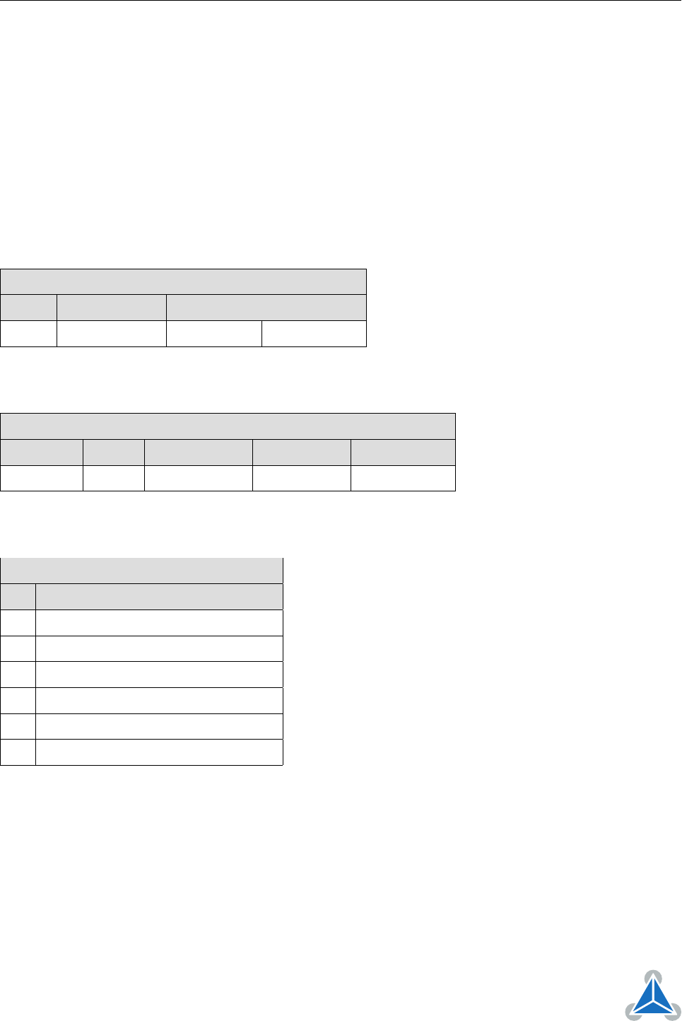
4.1.1 Object 2005
h
: Limit Switches
This object defines which limit switches are to be used. Bit 0 stands for the left and bit 1 stands for the
right limit switch. If a bit is set, the corresponding limit switch will not be used. So this object has to be set
to the value 3 if limit switches are not connected. The object can only be written when the drive is in the
SWITCHED_ON_DISABLED state (but is always readable).
The limit switches can also be inverted using bit 2 and bit 3:
• Bit 2 inverts the left limit switch
• Bit 3 inverts the right limit switch
The polarity of the home switch can be set using bit 5.
Object Description
Index Name Object Type Data Type
2005
h
Limit switches Variable UNSIGNED32
Table 50: Object Description (2005
h
)
Entry Description
Sub-index Access PDO Mapping Value Range Default Value
0 rw no 0. . . 63 0
Table 51: Entry Description (2005
h
)
Bit Definitions
Bit Definition
0 Left limit switch deactivated if set.
1 Right limit switch deactivated if set.
2 Left limit switch inverted if set.
3 Right limit switch inverted if set.
4 Home switch deactivated if set.
5 Home switch inverted if set.
Table 52: Bit Definitions (2005
h
)
4.1.2 Object 200D
h
: Status Flags
This object provides information about the actual module status flags. (0: not active, 1: active).
This object is organized bit-wise. The bits have the following meaning:
Bit 0: OVERCURRENT
Bit 1: UNDERVOLTAGE
©2018 TRINAMIC Motion Control GmbH & Co. KG, Hamburg, Germany
Terms of delivery and rights to technical change reserved.
Download newest version at www.trinamic.com