
User Manual


Table Of Contents
- 1 Preface
- 2 Communication
- 3 Communication area
- 3.1 Detailed object specifications
- 3.1.1 Object 1000h: Device Type
- 3.1.2 Object 1001h: Error Register
- 3.1.3 Object 1005h: COB-ID SYNC Message
- 3.1.4 Object 1008h: Manufacturer Device Name
- 3.1.5 Object 1009h: Manufacturer Hardware Version
- 3.1.6 Object 100Ah: Manufacturer Software Version
- 3.1.7 Object 100Ch: Guard Time
- 3.1.8 Object 100Dh: Life Time Factor
- 3.1.9 Object 1010h: Store Parameters
- 3.1.10 Object 1011h: Restore Parameters
- 3.1.11 Object 1014h: COB-ID Emergency Object
- 3.1.12 Object 1015h: Inhibit Time EMCY
- 3.1.13 Object 1016h: Consumer Heartbeat Time
- 3.1.14 Object 1017h: Producer Heartbeat Time
- 3.1.15 Object 1018h: Identity Object
- 3.1.16 Object 1029h: Error Behaviour
- 3.1.17 Objects 1400h – 1403h: Receive PDO Communication Parameter
- 3.1.18 Objects 1600h – 1603h: Receive PDO Mapping Parameter
- 3.1.19 Objects 1800h – 1803h: Transmit PDO Communication Parameter
- 3.1.20 Objects 1A00h – 1A03h: Transmit PDO Mapping Parameter
- 3.1 Detailed object specifications
- 4 Manufacturer specific area
- 4.1 Detailed object specifications
- 4.1.1 Object 2005h: Limit Switches
- 4.1.2 Object 200Dh: Status Flags
- 4.1.3 Object 200Eh: Supply Voltage
- 4.1.4 Object 200Fh: Driver Temperatur
- 4.1.5 Object 2010h: Motor Settings
- 4.1.6 Object 2020h: Limits
- 4.1.7 Object 2030h: Torque Mode Settings
- 4.1.8 Object 2040h: Velocity Mode Settings
- 4.1.9 Object 2050h: Position Mode Settings
- 4.1.10 Object 2055h: Commutation Mode
- 4.1.11 Object 2056h: Velocity Ramp Mode
- 4.1.12 Object 2060h: Open Loop Settings
- 4.1.13 Object 2080h: ABN Encoder Settings
- 4.1.14 Object 2100h: Home Offset Display
- 4.1.15 Object 2702h: Digital Inputs
- 4.1.16 Object 2703h: Digital Outputs
- 4.1.17 Object 2704h: CAN Bit Rate
- 4.1.18 Object 2705h: Node ID
- 4.1.19 Object 2706h: User Variables
- 4.1.20 Object 270Eh: Analog Inputs
- 4.1 Detailed object specifications
- 5 Profile specific area
- 5.1 Detailed object specifications
- 5.1.1 Object 605Ah: Quick Stop Option Code
- 5.1.2 Object 605Bh: Shutdown Option Code
- 5.1.3 Object 605Ch: Disable Operation Option Code
- 5.1.4 Object 605Dh: Halt Option Code
- 5.1.5 Object 605Eh: Fault Reaction Option Code
- 5.1.6 Object 6060h: Modes of Operation
- 5.1.7 Object 6061h: Modes of Operation Display
- 5.1.8 Object 608Fh: Position Encoder Resolution
- 5.1.9 Object 6099h: Homing Speeds
- 5.1.10 Object 60FDh: Digital Inputs
- 5.1.11 Object 6502h: Supported Drive Modes
- 5.1 Detailed object specifications
- 6 Profile Position Mode
- 6.1 Detailed Object Specifications
- 6.2 Detailed Object Specifications
- 6.2.1 Object 6040h: Control Word
- 6.2.2 Object 6041h: Status Word
- 6.2.3 Object 6062h: Position Demand Value
- 6.2.4 Object 6063h: Position Actual Internal Value
- 6.2.5 Object 6064h: Position Actual Value
- 6.2.6 Object 6067h: Position Window
- 6.2.7 Object 606Ch: Velocity Actual Value
- 6.2.8 Object 607Ah: Target Position
- 6.2.9 Object 607Dh: Software Position Limit
- 6.2.10 Object 6081h: Profile Velocity (pp)
- 6.2.11 Object 6082h: End Velocity
- 6.2.12 Object 6083h: Profile Acceleration
- 6.2.13 Object 6084h: Profile Deceleration
- 6.2.14 Object 6085h: Quick Stop Deceleration
- 6.3 How to move a Motor in pp Mode
- 7 Profile Velocity Mode
- 7.1 Detailed Object Specifications
- 7.1.1 Object 6040h: Control Word
- 7.1.2 Object 6041h: Status Word
- 7.1.3 Object 6062h: Position Demand Value
- 7.1.4 Object 6063h: Position Actual Internal Value
- 7.1.5 Object 6064h: Position Actual Value
- 7.1.6 Object 606Ch: Velocity Actual Value
- 7.1.7 Object 607Dh: Software Position Limit
- 7.1.8 Object 6083h: Profile Acceleration
- 7.1.9 Object 6085h: Quick Stop Deceleration
- 7.1.10 Object 60FFh: Target Velocity
- 7.2 How to move a Motor in pv Mode
- 7.1 Detailed Object Specifications
- 8 Homing mode
- 9 Cyclic synchronous Torque Mode
- 10 Emergency Messages (EMCY)
- 11 Figures Index
- 12 Tables Index
- 13 Supplemental Directives
- 14 Revision History
PD42-x-1670 CANopen Firmware Manual • Firmware Version V2.0 | Document Revision V1.0 • 2018-Nov-07
22 / 86
• Communication error
• Application error
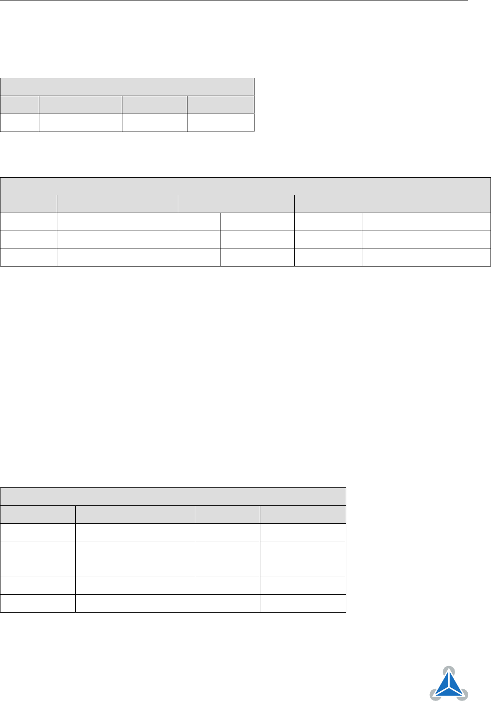
Object Description
Index Name Object Type Data Type
1029
h
Error behaviour Array UNSIGNED8
Table 40: Object Description (1029
h
)
Entry Description
Sub-index Description Access PDO Mapping Value Range Default Value
00
h
Number of error classes ro no — 2
01
h
Communication error rw no UNSIGNED8 0 (enter stopped state)
02
h
Application error rw no UNSIGNED8 1 (remain in current state)
Table 41: Entry Description (1029
h
)
3.1.17 Objects 1400
h
– 1403
h
: Receive PDO Communication Parameter
This object contains the communication parameters for the RPDOs which the device is able to receive. The
sub-index 00
h
contains the number of valid entries within the communication record. Its value normally is
2, as this object consists of two other entries.
Sub-index 01
h
contains the COB-ID used by this PDO (in bits 10. . . 0). Bit 30 (RTR bit) defines if this PDO
uses RTRs. As RTRs are not supported for PDOs by this CANopen implementation, this bit must always
be set in order to turn off RTR support for this PDO. Bit 31 defines if this PDO is active or not. If this bit
is set, the PDO is inactive, and if this bit is clear, the PDO is active. Before making any changes to a PDO
definition, set this bit to inactivate the PDO.
Sub-Index 02
h
contains the transmission type of the RPDO. This can be FF
h
or FE
h
for event-driven, or 00
h
for synchronous.
Object Description
Index Name Object Type Data Type
1400
h
– 1403
h
Receive PDO parameter RECORD RPDO CommPar
1400
h
RPDO 1 RECORD RPDO CommPar
1401
h
RPDO 2 RECORD RPDO CommPar
1402
h
RPDO 3 RECORD RPDO CommPar
1403
h
RPDO 4 RECORD RPDO CommPar
Table 42: Object Description (1400
h
)
©2018 TRINAMIC Motion Control GmbH & Co. KG, Hamburg, Germany
Terms of delivery and rights to technical change reserved.
Download newest version at www.trinamic.com