
User Manual


Table Of Contents
- 1 Preface
- 2 Communication
- 3 Communication area
- 3.1 Detailed object specifications
- 3.1.1 Object 1000h: Device Type
- 3.1.2 Object 1001h: Error Register
- 3.1.3 Object 1005h: COB-ID SYNC Message
- 3.1.4 Object 1008h: Manufacturer Device Name
- 3.1.5 Object 1009h: Manufacturer Hardware Version
- 3.1.6 Object 100Ah: Manufacturer Software Version
- 3.1.7 Object 100Ch: Guard Time
- 3.1.8 Object 100Dh: Life Time Factor
- 3.1.9 Object 1010h: Store Parameters
- 3.1.10 Object 1011h: Restore Parameters
- 3.1.11 Object 1014h: COB-ID Emergency Object
- 3.1.12 Object 1015h: Inhibit Time EMCY
- 3.1.13 Object 1016h: Consumer Heartbeat Time
- 3.1.14 Object 1017h: Producer Heartbeat Time
- 3.1.15 Object 1018h: Identity Object
- 3.1.16 Object 1029h: Error Behaviour
- 3.1.17 Objects 1400h – 1403h: Receive PDO Communication Parameter
- 3.1.18 Objects 1600h – 1603h: Receive PDO Mapping Parameter
- 3.1.19 Objects 1800h – 1803h: Transmit PDO Communication Parameter
- 3.1.20 Objects 1A00h – 1A03h: Transmit PDO Mapping Parameter
- 3.1 Detailed object specifications
- 4 Manufacturer specific area
- 4.1 Detailed object specifications
- 4.1.1 Object 2005h: Limit Switches
- 4.1.2 Object 200Dh: Status Flags
- 4.1.3 Object 200Eh: Supply Voltage
- 4.1.4 Object 200Fh: Driver Temperatur
- 4.1.5 Object 2010h: Motor Settings
- 4.1.6 Object 2020h: Limits
- 4.1.7 Object 2030h: Torque Mode Settings
- 4.1.8 Object 2040h: Velocity Mode Settings
- 4.1.9 Object 2050h: Position Mode Settings
- 4.1.10 Object 2055h: Commutation Mode
- 4.1.11 Object 2056h: Velocity Ramp Mode
- 4.1.12 Object 2060h: Open Loop Settings
- 4.1.13 Object 2080h: ABN Encoder Settings
- 4.1.14 Object 2100h: Home Offset Display
- 4.1.15 Object 2702h: Digital Inputs
- 4.1.16 Object 2703h: Digital Outputs
- 4.1.17 Object 2704h: CAN Bit Rate
- 4.1.18 Object 2705h: Node ID
- 4.1.19 Object 2706h: User Variables
- 4.1.20 Object 270Eh: Analog Inputs
- 4.1 Detailed object specifications
- 5 Profile specific area
- 5.1 Detailed object specifications
- 5.1.1 Object 605Ah: Quick Stop Option Code
- 5.1.2 Object 605Bh: Shutdown Option Code
- 5.1.3 Object 605Ch: Disable Operation Option Code
- 5.1.4 Object 605Dh: Halt Option Code
- 5.1.5 Object 605Eh: Fault Reaction Option Code
- 5.1.6 Object 6060h: Modes of Operation
- 5.1.7 Object 6061h: Modes of Operation Display
- 5.1.8 Object 608Fh: Position Encoder Resolution
- 5.1.9 Object 6099h: Homing Speeds
- 5.1.10 Object 60FDh: Digital Inputs
- 5.1.11 Object 6502h: Supported Drive Modes
- 5.1 Detailed object specifications
- 6 Profile Position Mode
- 6.1 Detailed Object Specifications
- 6.2 Detailed Object Specifications
- 6.2.1 Object 6040h: Control Word
- 6.2.2 Object 6041h: Status Word
- 6.2.3 Object 6062h: Position Demand Value
- 6.2.4 Object 6063h: Position Actual Internal Value
- 6.2.5 Object 6064h: Position Actual Value
- 6.2.6 Object 6067h: Position Window
- 6.2.7 Object 606Ch: Velocity Actual Value
- 6.2.8 Object 607Ah: Target Position
- 6.2.9 Object 607Dh: Software Position Limit
- 6.2.10 Object 6081h: Profile Velocity (pp)
- 6.2.11 Object 6082h: End Velocity
- 6.2.12 Object 6083h: Profile Acceleration
- 6.2.13 Object 6084h: Profile Deceleration
- 6.2.14 Object 6085h: Quick Stop Deceleration
- 6.3 How to move a Motor in pp Mode
- 7 Profile Velocity Mode
- 7.1 Detailed Object Specifications
- 7.1.1 Object 6040h: Control Word
- 7.1.2 Object 6041h: Status Word
- 7.1.3 Object 6062h: Position Demand Value
- 7.1.4 Object 6063h: Position Actual Internal Value
- 7.1.5 Object 6064h: Position Actual Value
- 7.1.6 Object 606Ch: Velocity Actual Value
- 7.1.7 Object 607Dh: Software Position Limit
- 7.1.8 Object 6083h: Profile Acceleration
- 7.1.9 Object 6085h: Quick Stop Deceleration
- 7.1.10 Object 60FFh: Target Velocity
- 7.2 How to move a Motor in pv Mode
- 7.1 Detailed Object Specifications
- 8 Homing mode
- 9 Cyclic synchronous Torque Mode
- 10 Emergency Messages (EMCY)
- 11 Figures Index
- 12 Tables Index
- 13 Supplemental Directives
- 14 Revision History
PD42-x-1670 CANopen Firmware Manual • Firmware Version V2.0 | Document Revision V1.0 • 2018-Nov-07
10 / 86
2.2 NMT State Machine
The finite state machine (FSM) or simply state machine is a model of behavior composed of a finite number
of states, transitions between those states, and actions. It shows which way the logic runs when certain
conditions are met.
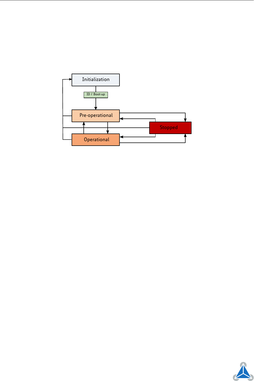
Starting and resetting the device is controlled via the state machine. The NMT state machine consists of
the states shown in figure 1.
Pre-operational
Operational
Stopped
Initialization
ID / Boot-up
Figure 1: NMT State Machine
After power-on or reset the device enters the Initialization state. After the device initialization is finished,
the device automatically transits to the
Pre-operational
state and indicates this state transition by send-
ing the boot-up message. This way the device indicates that it is ready to work. A device that stays in
Pre-operational state may start to transmit SYNC-, time stamp- or heartbeat message. In contrast to the
PDO communication that is disabled in this state, the device can communicate via SDO.
The PDO communication is only possible within the
Operational
state. During Operational state the
device can use all supported communication objects.
A device that was switched to the
Stopped
state only reacts on received NMT commands. In addition the
device indicates the current NMT state by supporting the error control protocol during Stopped state.
The transitions between states are made by issuing a network management (NMT) communication object
to the device. The NMT protocols are used to generate state machine change commands (e.g. to start and
stop the device), detect remote device boot-ups and error conditions.
The Heartbeat message of a CANopen device contains the device status of the NMT state machine and is
sent cyclically by the CANopen device.
The NMT state machine (or DS301 state machine) is not to be confused with the DS402 state machine.
There is only one NMT state machine for the entire device, but for each motor there is a DS402 state
machine which controls the motor. There are no links between these state machines, with one exception:
When the NMT state machine is being switched to the stopped state, all DS402 state machines that are in
OPERATION_ENABLED state will be switch to FAULT state.
©2018 TRINAMIC Motion Control GmbH & Co. KG, Hamburg, Germany
Terms of delivery and rights to technical change reserved.
Download newest version at www.trinamic.com