
User Manual


PD42-x-1140 Hardware Manual (V1.03 / 2018-JAN-25) 14
Copyright © 2012-2018, TRINAMIC Motion Control GmbH & Co. KG
2. BUS TERMINATION:
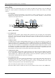
Especially for longer busses and/or multiple nodes connected to the bus and/or high communication
speeds, the bus should be properly terminated at both ends. The PD42-x-1140 does not integrate any
termination resistor. Therefore, 120 Ohm termination resistors at both ends of the bus have to be
added externally.
3. NUMBER OF NODES:
The bus transceiver used for the PD42-x-1140 (TJA1050T) supports at least 110 nodes under optimum
conditions. Practically achievable number of nodes per CAN bus highly depend on bus length (longer
bus -> less nodes) and communication speed (higher speed -> less nodes).
4.4.2 Multi-purpose I/O
An 8pin 2mm pitch single row connector is available for all multi-purpose inputs and outputs.
8
1
Pin
Label
Direction
Description
1
GND
Power (GND)
System and signal ground
2
VDD
Power (Supply)
VDD, connected to VDD pin of the power and
communication connector
3
OUT_0
Output
Open-drain output (max. 1A)
Integrated freewheeling diode to VDD
4
OUT_1
Output
+5V supply output (max. 100mA)
Can be switched on/off in software
5
IN_0
Input
Dedicated analog input,
Input voltage range: 0..+10V
Resolution: 12bit (0..4095)
6
IN_1,
STOP_L,
ENC_A
Input
General purpose digital input (+24V compatible)
Alternate function 1: left stop switch input
Alternate function 2: external incremental
encoder channel A input
7
IN_2,
STOP_R,
ENC_B
Input
General purpose digital input (+24V compatible)
Alternate function 1: right stop switch input
Alternate function 2: external incremental
encoder channel B input
8
IN_3,
HOME,
ENC_N
Input
General purpose digital input (+24V compatible)
Alternate function 1: home switch input
Alternate function 2: external incremental
encoder index / zero channel input
Table 4.4 Multipurpose I/O connector
Note:
- All inputs have resistor based voltage input dividers with protection diodes. These resistors also
ensure a valid GND level when left unconnected.
- For all digital inputs (IN_1, IN_2, IN_3) a 2k2 pull-up resistor to +5V can be activated (default setting
with all more recent TMCL firmware versions). Then these inputs have a default (unconnected) logic
level of 1 and an external switch to GND can be connected. This might be especially interesting in
case these inputs are used as STOP_L / STOP_R and HOME switch inputs (alternate function 1) or as
encoder input for an external incremental A/B/N encoder with open-collector outputs (pull-ups are not
necessary for encoder with push-pull outputs).