
User Manual


PD42-x-1140 Hardware Manual (V1.03 / 2018-JAN-25) 13
Copyright © 2012-2018, TRINAMIC Motion Control GmbH & Co. KG
node
n - 1
node
n
Slave Slave
termination
resistor
(120R)
+5V
GND
pull-up (680R)
pull-down (680R)
RS485- / RS485B
termination
resistor
(220R)
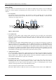
RS485+ / RS485A
Figure 4.3: Bus lines with resistor (Bias) network on one side, only
Or add resistor (Bias) network at both ends of the bus (like Profibus™ termination):
node
n - 1
node
n
Slave Slave
termination
resistor
(220R)
+5V
GND
pull-up (390R)
pull-down (390R)
RS485- / RS485B
RS485+ / RS485A
termination
resistor
(220R)
+5V
GND
pull-up (390R)
pull-down (390R)
Figure 4.4: Bus lines with resistor (Bias) network at both ends
Certain RS485 interface converters available for PCs already include these additional resistors (e.g. USB-
2-485 with bias network at one end of the bus).
4.4.1.3 CAN
For remote control and communication with a host system the PD42-x-1140 provides a CAN bus interface.
Please note that the CAN interface is not available in case USB is connected. For proper operation the following
items should be taken into account when setting up a CAN network:
1. BUS STRUCTURE:
The network topology should follow a bus structure as closely as possible. That is, the connection
between each node and the bus itself should be as short as possible. Basically, it should be short
compared to the length of the bus.
c:>
node
1
node
n
- 1
node
n
Host
Slave Slave Slave
CAN
termination
resistor
(120 Ohm)
termination
resistor
(120 Ohm)
}
keep distance as
short as possible
Figure 4.5 CAN bus structure