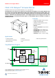
PANDRIVE™ PANdrive™ for Stepper Motors PD42-1270 CANopen® Firmware Manual Firmware Version V3.19 | Document Revision V1.0 • 2017-Mar-02 The PD42-1270 is an easy to use, single axis controller/driver PANdrive™ for 2-phase bipolar stepper motors with separate differential encoder and separate home and stop switch inputs. Dynamic current control, and quiet, smooth and efficient operation are combined with stealthChop™, dcStep™, stallGuard™and coolStep™features.
PD42-1270 CANopen® Firmware Manual • Firmware Version V3.19 | Document Revision V1.0 • 2017-Mar-02 2 / 106 Contents 1 Preface 1.1 General Features of this CANopen Implementation . . . . 1.2 Abbreviations used in this Manual . . . . . . . . . . . . . . 1.3 Firmware Update . . . . . . . . . . . . . . . . . . . . . . . . 1.4 Trinamic’s unique Features — easy to use with CANopen 1.4.1 stallGuard2 . . . . . . . . . . . . . . . . . . . . . . . 1.4.2 coolStep . . . . . . . . . . . . . . . . . . . . . . . . . .
PD42-1270 CANopen® Firmware Manual • Firmware Version V3.19 | Document Revision V1.0 • 2017-Mar-02 4.2.13 4.2.14 4.2.15 4.2.16 4.2.17 4.2.18 4.2.19 4.2.20 4.2.21 4.2.22 4.2.23 4.2.24 4.2.25 4.2.26 4.2.27 4.2.28 4.2.29 4.2.30 4.2.31 4.2.32 4.2.33 4.2.34 4.2.35 4.2.36 4.2.37 4.2.38 4.2.39 4.2.40 4.2.41 4.2.42 4.2.43 4.2.44 4.2.45 4.2.46 4.2.47 4.2.48 4.2.49 4.2.50 4.2.51 4.2.52 4.2.53 4.2.54 4.2.55 4.2.56 4.2.57 4.2.58 4.2.59 4.2.60 4.2.61 4.2.62 4.2.63 Object 2013h : Profile D1 . . . . . . . . . . . . . .
PD42-1270 CANopen® Firmware Manual • Firmware Version V3.19 | Document Revision V1.0 • 2017-Mar-02 4 / 106 5 Profile specific Area 5.1 Detailed Object Specifications . . . . . . . . . . . . . . 5.1.1 Object 605Ah : Quick Stop Option Code . . . . 5.1.2 Object 605Bh : Shutdown Option Code . . . . 5.1.3 Object 605Ch : Disable Operation Option Code 5.1.4 Object 605Dh : Halt Option Code . . . . . . . . 5.1.5 Object 605Eh : Fault Reaction Option Code . . 5.1.6 Object 6060h : Modes of Operation . . . . . . . 5.1.
PD42-1270 CANopen® Firmware Manual • Firmware Version V3.19 | Document Revision V1.0 • 2017-Mar-02 8 Homing Mode 8.1 Homing Methods . . . . . . . . . . . . . . . . . . . . . . . . . . . . . . . . . . . . 8.1.1 Homing Method 1: Homing on negative Limit Switch and Index Pulse . 8.1.2 Homing Method 2: Homing on positive Limit Switch and Index Pulse . 8.1.3 Homing Method 3: Homing on positive Home Switch and Index Pulse . 8.1.4 Homing Method 5: Homing on negative Home Switch and Index Pulse 8.1.
PD42-1270 CANopen® Firmware Manual • Firmware Version V3.19 | Document Revision V1.0 • 2017-Mar-02 1 6 / 106 Preface This document specifies objects and modes of operation of the Trinamic PD42-1270 stepper motor control PANdrive™ with CANopen firmware. The CANopen firmware is designed to fulfill the CANopen DS402 and DS301 standards. This manual assumes that the reader is already familiar with the basics of the CANopen protocol, defined by the DS301 and DS402 standards of the CAN-CiA.
PD42-1270 CANopen® Firmware Manual • Firmware Version V3.19 | Document Revision V1.0 • 2017-Mar-02 7 / 106 Further Characteristics • SYNC: consumer (TPDOs 3 are synchronous PDOs) • Emergency: producer • RTR: supported only for node guarding/life guarding • Heartbeat: consumer and producer 1.
PD42-1270 CANopen® Firmware Manual • Firmware Version V3.19 | Document Revision V1.0 • 2017-Mar-02 8 / 106 CAN interface of the module. To reset the module to bootloader mode, write the hex number 12345678h to object 5FFFh . Both LEDs of the PD42-1270 will turn on and remain lighting. Now the new firmware can be uploaded using the Firmware Update Tool of the TMCL-IDE 3.0. 1.4 1.4.
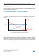
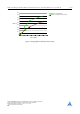
PD42-1270 CANopen® Firmware Manual • Firmware Version V3.19 | Document Revision V1.0 • 2017-Mar-02 0,9 Efficiency with coolStep 0,8 Efficiency with 50v torque reserve 0,7 0,6 0,5 Efficiency 0,4 0,3 0,2 0,1 0 0 50 100 150 200 250 300 350 Velocity [RPM] Figure 2: Energy Efficiency Example with coolStep ©2017 TRINAMIC Motion Control GmbH & Co. KG, Hamburg, Germany Terms of delivery and rights to technical change reserved. Download newest version at www.trinamic.com Read entire documentation.
PD42-1270 CANopen® Firmware Manual • Firmware Version V3.19 | Document Revision V1.0 • 2017-Mar-02 2 2.1 10 / 106 Communication Reference Model The application layer comprises a concept to configure and communicate real-time-data as well as the mechanisms for synchronization between devices. The functionality which the application layer offers to an application is logically divided over different service data objects (SDO) in the application layer.
PD42-1270 CANopen® Firmware Manual • Firmware Version V3.19 | Document Revision V1.0 • 2017-Mar-02 11 / 106 Service Types Type Definition Local service Involves only the local service object. The application issues a request to its local service object that executes the requested service without communicating with peer service object(s). Unconfirmed service Involves one or more peer service objects. The application issues a request to its local service object.
PD42-1270 CANopen® Firmware Manual • Firmware Version V3.19 | Document Revision V1.0 • 2017-Mar-02 2.2 12 / 106 NMT State Machine The finite state machine (FSM) or simply state machine is a model of behavior composed of a finite number of states, transitions between those states, and actions. It shows which way the logic runs when certain conditions are met. Starting and resetting the device is controlled via the state machine. The NMT state machine consists of the states shown in figure 3.
PD42-1270 CANopen® Firmware Manual • Firmware Version V3.19 | Document Revision V1.0 • 2017-Mar-02 13 / 106 CANopen device profile CiA DSP 402 Modes of operation: Profile Position (pp) Profile Velocity (pv) Homing (hm) ... Device control state machine CANopen Communication Profile CiA DS301 NMT State Machine CAN Figure 4: Communication Architecture 2.
PD42-1270 CANopen® Firmware Manual • Firmware Version V3.19 | Document Revision V1.0 • 2017-Mar-02 14 / 106 Application Communication Object dictionary State machine Application object Entry 1 Entry 2 Communication object Communication object Application object Communication object Application object Entry n Application object Communication object Bus system Process Figure 5: Device Model 2.4 Object Dictionary The most important part of a device profile is the object dictionary description.
PD42-1270 CANopen® Firmware Manual • Firmware Version V3.19 | Document Revision V1.0 • 2017-Mar-02 15 / 106 The communication profile area at indices 1000h through 1FFFh contains the communication specific parameters for the CAN network. These entries are common to all devices. The manufacturer segment at indices 2000h through 5FFFh contains manufacturer specific objects. These objects control the special features of the Trinamic PD42-1270 motion control device.
PD42-1270 CANopen® Firmware Manual • Firmware Version V3.19 | Document Revision V1.0 • 2017-Mar-02 3 16 / 106 Communication Area The communication area contains all objects that define the communication parameters of the CANopen device according to the DS301 standard. 3.1 Detailed Object Specifications 3.1.1 Object 1000h : Device Type This object contains information about the device type. The object 1000h describes the type of device and its functionality.
PD42-1270 CANopen® Firmware Manual • Firmware Version V3.19 | Document Revision V1.0 • 2017-Mar-02 17 / 106 Error Register Bits Bit Definition 0 Generic error 1 Current 2 Voltage 3 Temperature 4 Communication error 5 Device profile specific 6 Reserved (always 0) 7 Manufacturer specific Table 9: Error Register Bits 3.1.3 Object 1005h : COB-ID SYNC Message This object defines the COB-ID of the synchronization object (SYNC). Further, it defines whether the module generates the SYNC.
PD42-1270 CANopen® Firmware Manual • Firmware Version V3.19 | Document Revision V1.0 • 2017-Mar-02 3.1.4 Object 1008h : Manufacturer Device Name This object contains the manufacturer device name. Object Description Index Name Object Type Data Type 1008h Manufacturer Device Name Variable Visible String Table 13: Object Description (1008h ) Entry Description Sub-index Access PDO Mapping Value Range Default Value 0 ro no — PD42-1270 Table 14: Entry Description (1008h ) 3.1.
PD42-1270 CANopen® Firmware Manual • Firmware Version V3.19 | Document Revision V1.0 • 2017-Mar-02 19 / 106 Entry Description Sub-index Access PDO Mapping Value Range Default Value 0 ro no — Depends on device, e.g. 1.0. Table 18: Entry Description (100Ah ) 3.1.7 Object 100Ch : Guard Time The objects at index 100Ch and 100Dh shall indicate the configured guard time respectively the life time factor.
PD42-1270 CANopen® Firmware Manual • Firmware Version V3.19 | Document Revision V1.0 • 2017-Mar-02 Note 20 / 106 This command can only be carried out if the module is in ready to switch on mode. There are several parameter groups: • Sub-index 0h : contains the largest sub-index that is supported. • Sub-index 1h : saves all parameters. • Sub-index 2h : saves communication parameters 100Ch , 100Dh , 1015h , 1017h , and 1029h . • Sub-index 3h : saves device profile parameters.
PD42-1270 CANopen® Firmware Manual • Firmware Version V3.19 | Document Revision V1.0 • 2017-Mar-02 21 / 106 Entry Description Sub-index Description Access PDO Mapping Value Range Default Value 01h Save all parameters rw no UNSIGNED32 — 02h Save communication parameters rw no UNSIGNED32 — 03h Save device profile parameters rw no UNSIGNED32 — 04h Save motor axis 0 parameters rw no UNSIGNED32 — Table 25: Entry Description (1010h ) 3.1.
PD42-1270 CANopen® Firmware Manual • Firmware Version V3.19 | Document Revision V1.0 • 2017-Mar-02 22 / 106 On read access, each sub-index provides information if it is possible to restore the parameter group. It reads 1 if yes and 0 if no. After the default values have been restored they will become active after the next rest or power cycle of the PD42-1270.
PD42-1270 CANopen® Firmware Manual • Firmware Version V3.19 | Document Revision V1.0 • 2017-Mar-02 23 / 106 Object Description Index Name Object Type Data Type 1015h COB-ID emergency object Variable UNSIGNED16 Table 31: Object Description (1015h ) Entry Description Sub-index Access PDO Mapping Value Range Default Value 0 rw no UNSIGNED16 0 Table 32: Entry Description (1015h ) 3.1.
PD42-1270 CANopen® Firmware Manual • Firmware Version V3.19 | Document Revision V1.0 • 2017-Mar-02 3.1.14 24 / 106 Object 1017h : Producer Heartbeat Time The producer heartbeat time defines the cycle time of the heartbeat. The producer heartbeat time is 0 if it is not used. The time has to be a multiple of 1ms.
PD42-1270 CANopen® Firmware Manual • Firmware Version V3.19 | Document Revision V1.0 • 2017-Mar-02 3.1.16 25 / 106 Object 1029h : Error Behaviour If a device failure is detected in operational state, the device can be configured to enter alternatively the stopped state or remain in the current state in case of a device failure.
PD42-1270 CANopen® Firmware Manual • Firmware Version V3.19 | Document Revision V1.
PD42-1270 CANopen® Firmware Manual • Firmware Version V3.19 | Document Revision V1.0 • 2017-Mar-02 27 / 106 Entry Description Sub-index Description Access Value Range Default Value 00h Number of mapped application objects in PDO rw 0. . .
PD42-1270 CANopen® Firmware Manual • Firmware Version V3.19 | Document Revision V1.
PD42-1270 CANopen® Firmware Manual • Firmware Version V3.19 | Document Revision V1.
PD42-1270 CANopen® Firmware Manual • Firmware Version V3.19 | Document Revision V1.0 • 2017-Mar-02 4 30 / 106 Manufacturer specific Area The manufacturer segment contains manufacturer specific objects. These objects control the special features of the Trinamic Motion Control device PD42-1270. 4.1 Objects related to coolStep Figure 6 shows an overview of the coolStep related objects for motor #0. Please bear in mind that the figure only shows one example for a drive.
PD42-1270 CANopen® Firmware Manual • Firmware Version V3.19 | Document Revision V1.0 • 2017-Mar-02 31 / 106 coolStep Adjustment Objects Object Name Description 2003h Absolute maximum current The maximum value is 255. This value means 100% of the maximum current of the module. The current adjustment is within the range 0. . . 255 and can be adjusted in 32 steps (0. . . 255 divided by eight; step 0 = 0. . . 7, step 1 = 8. . . 15 and so on).
PD42-1270 CANopen® Firmware Manual • Firmware Version V3.19 | Document Revision V1.0 • 2017-Mar-02 4.2 Detailed Object Specifications 4.2.1 Object 2000h : Microstep Resolution 32 / 106 This object sets the microstep resolution of the drive. A value of 8 selects 256 (28 ) microsteps per full step.
PD42-1270 CANopen® Firmware Manual • Firmware Version V3.19 | Document Revision V1.
PD42-1270 CANopen® Firmware Manual • Firmware Version V3.19 | Document Revision V1.0 • 2017-Mar-02 4.2.5 34 / 106 Object 2004h : Standby Current This object defines the current used when the motor is standing (two seconds after the last move). A value of 255 means 100% of the maximum current of the drive.
PD42-1270 CANopen® Firmware Manual • Firmware Version V3.19 | Document Revision V1.0 • 2017-Mar-02 35 / 106 Bit Definitions Bit Definition 0 Left limit switch deactivated, if set. 1 Right limit switch deactivated, if set. 2 Left limit switch inverted, if set. 3 Right limit switch inverted, if set. 4 Home switch deactivated, if set. 5 Home switch inverted, if set. Table 63: Bit Definitions (2005h ) 4.2.
PD42-1270 CANopen® Firmware Manual • Firmware Version V3.19 | Document Revision V1.0 • 2017-Mar-02 36 / 106 Entry Description Sub-index Description Access PDO Mapping Value Range Default Value 1 Null channel polarity rw no 0/1 0 2 Direction of rotation rw no 0/1 0 3 Initialize position rw no 0/1 1 Table 67: Entry Description (200Bh ) 4.2.9 Object 200Ch : Brake Current Feed This object configures how much current has to be fed into the brake to apply and to release it.
PD42-1270 CANopen® Firmware Manual • Firmware Version V3.19 | Document Revision V1.0 • 2017-Mar-02 37 / 106 Entry Description Sub-index Access PDO Mapping Value Range Default Value 0 rw no 0. . . 268435455 0 Table 71: Entry Description (2010h ) 4.2.11 Object 2011h : Profile A1 This object contains the acceleration value used for ramping up from the start velocity (object 2011h , see section 4.2.10) to the velocity V1 (object (h 2012), see section 4.2.12).
PD42-1270 CANopen® Firmware Manual • Firmware Version V3.19 | Document Revision V1.0 • 2017-Mar-02 4.2.13 38 / 106 Object 2013h : Profile D1 This object contains the deceleration value used for decelerating from the maximum positioning velocity to the velocity V1 (object 2012h , see section 4.2.12).
PD42-1270 CANopen® Firmware Manual • Firmware Version V3.19 | Document Revision V1.0 • 2017-Mar-02 39 / 106 Object Description Index Name Object Type Data Type 2089h Setting Delay Variable UNSIGNED16 Table 80: Object Description (2089h ) Entry Description Sub-index Access PDO Mapping Value Range Default Value 0 rw no 0. . . 400 0 Table 81: Entry Description (2089h ) 4.2.
PD42-1270 CANopen® Firmware Manual • Firmware Version V3.19 | Document Revision V1.0 • 2017-Mar-02 40 / 106 Entry Description Sub-index Access PDO Mapping Value Range Default Value 0 ro no 0/179 179 Table 85: Entry Description (208Eh ) 4.2.18 Object 2092h : Chopper Blank Time This object serves for selecting the comparator blank time. This time needs to safely cover the switching event and the duration of the ringing on the sense resistor. For low current drivers, a setting of 1 or 2 is good.
PD42-1270 CANopen® Firmware Manual • Firmware Version V3.19 | Document Revision V1.0 • 2017-Mar-02 4.2.20 41 / 106 Object 2094h : Chopper Hysteresis Decrement This object serves for the hysteresis decrement setting. This setting determines the slope of the hysteresis during on time and during fast decay time.
PD42-1270 CANopen® Firmware Manual • Firmware Version V3.19 | Document Revision V1.0 • 2017-Mar-02 4.2.22 42 / 106 Object 2096h : Chopper Hysteresis Start This object provides the hysteresis start setting. Please notice that this value is an offset to the hysteresis end value.
PD42-1270 CANopen® Firmware Manual • Firmware Version V3.19 | Document Revision V1.0 • 2017-Mar-02 43 / 106 Object Description Index Name Object Type Data Type 2098h Smart Energy Current Minimum Variable UNSIGNED8 Table 98: Object Description (2098h ) Entry Description Sub-index Access PDO Mapping Value Range Default Value 0 rw no 0/1 0 Table 99: Entry Description (2098h ) 4.2.
PD42-1270 CANopen® Firmware Manual • Firmware Version V3.19 | Document Revision V1.0 • 2017-Mar-02 44 / 106 Object Description Index Name Object Type Data Type 209Ah Smart Energy Hysteresis Variable UNSIGNED8 Table 102: Object Description (209Ah ) Entry Description Sub-index Access PDO Mapping Value Range Default Value 0 rw no 0. . . 15 0 Table 103: Entry Description (209Ah ) 4.2.27 Object 209Bh : Smart Energy Current Up Step This object sets the current increment step.
PD42-1270 CANopen® Firmware Manual • Firmware Version V3.19 | Document Revision V1.0 • 2017-Mar-02 45 / 106 Object Description Index Name Object Type Data Type 209Ch Smart Energy Hysteresis Start Variable UNSIGNED8 Table 106: Object Description (209Ch ) Entry Description Sub-index Access PDO Mapping Value Range Default Value 0 rw no 0. . . 15 0 Table 107: Entry Description (209Ch ) 4.2.
PD42-1270 CANopen® Firmware Manual • Firmware Version V3.19 | Document Revision V1.0 • 2017-Mar-02 46 / 106 Object Description Index Name Object Type Data Type 209Eh stallGuard2 Threshold Variable SIGNED8 Table 110: Object Description (209Eh ) Entry Description Sub-index Access PDO Mapping Value Range Default Value 0 rw no -63. . . 63 0 Table 111: Entry Description (209Eh ) 4.2.
PD42-1270 CANopen® Firmware Manual • Firmware Version V3.19 | Document Revision V1.0 • 2017-Mar-02 47 / 106 Object Description Index Name Object Type Data Type 20A3h Vsense Variable UNSIGNED8 Table 114: Object Description (20A3h ) Entry Description Sub-index Access PDO Mapping Value Range Default Value 0 rw no 0/1 0 Table 115: Entry Description (20A3h ) 4.2.33 Object 20A4h : Stop on Stall Below this speed the motor will not be stopped.
PD42-1270 CANopen® Firmware Manual • Firmware Version V3.19 | Document Revision V1.0 • 2017-Mar-02 48 / 106 Entry Description Sub-index Access PDO Mapping Value Range Default Value 0 rw no 0. . . 2147483647 0 Table 119: Entry Description (20A5h ) 4.2.35 Object 20B0h : PWM Threshold Speed The stealthChop feature will be switched on when the value of this object is greater than zero and the actual velocity is higher than the value set by this object.
PD42-1270 CANopen® Firmware Manual • Firmware Version V3.19 | Document Revision V1.0 • 2017-Mar-02 4.2.37 49 / 106 Object 20B2h : PWM Amplitude Maximum PWM amplitude when switching to stealthChop mode. Do not set too low. Values above 64 are recommended. Object Description Index Name Object Type Data Type 20B2h PWM Amplitude Variable UNSIGNED8 Table 124: Object Description (20B2h ) Entry Description Sub-index Access PDO Mapping Value Range Default Value 0 rw no 0. . .
PD42-1270 CANopen® Firmware Manual • Firmware Version V3.19 | Document Revision V1.0 • 2017-Mar-02 50 / 106 Object Description Index Name Object Type Data Type 20B4h dcStep Time Variable UNSIGNED16 Table 128: Object Description (20B4h ) Entry Description Sub-index Access PDO Mapping Value Range Default Value 0 rw no 0. . . 1023 0 Table 129: Entry Description (20B4h ) 4.2.40 Object 20B5h : dcStep stallGuard This setting controls stall detection in dcStep mode.
PD42-1270 CANopen® Firmware Manual • Firmware Version V3.19 | Document Revision V1.0 • 2017-Mar-02 51 / 106 Entry Description Sub-index Access PDO Mapping Value Range Default Value 0 rw no 0. . . 16777215 0 Table 133: Entry Description (20B6h ) 4.2.42 Object 20B7h : High Speed Chopper Mode The motor driver will switch to a different chopper mode when this object is set to 1 and the measured speed is greater than the threshold speed set by object 20B6h (see section 4.2.41).
PD42-1270 CANopen® Firmware Manual • Firmware Version V3.19 | Document Revision V1.0 • 2017-Mar-02 expired. The smooth transition avoids a motor jerk upon power down. • 0=instant power down. • 15=longest possible power down ramp. Object Description Index Name Object Type Data Type 20B9h Power Down Ramp Variable UNSIGNED8 Table 138: Object Description (20B9h ) Entry Description Sub-index Access PDO Mapping Value Range Default Value 0 rw no 0. . .
PD42-1270 CANopen® Firmware Manual • Firmware Version V3.19 | Document Revision V1.0 • 2017-Mar-02 Entry Description Sub-index Access PDO Mapping Value Range Default Value 0 ro no 0. . . 1023 0 Table 143: Entry Description (2101h ) 4.2.47 Object 2102h : Driver Error Flags This object shows the error flags of the motor driver IC.
PD42-1270 CANopen® Firmware Manual • Firmware Version V3.19 | Document Revision V1.0 • 2017-Mar-02 54 / 106 Object Description Index Name Object Type Data Type 2107h Microstep resolution display Variable UNSIGNED8 Table 147: Object Description (2107h ) Entry Description Sub-index Access PDO Mapping Value Range Default Value 0 ro no 0. . . 8 8 Table 148: Entry Description (2107h ) 4.2.
PD42-1270 CANopen® Firmware Manual • Firmware Version V3.19 | Document Revision V1.0 • 2017-Mar-02 55 / 106 Entry Description Sub-index Access PDO Mapping Value Range Default Value 0 ro no 0. . . 255 — Table 152: Entry Description (2121h ) 4.2.51 Object 2122h : Measured Velocity This object contains the velocity measured by the motor driver. This value is important only when the motor driver is operating in dcStep mode.
PD42-1270 CANopen® Firmware Manual • Firmware Version V3.19 | Document Revision V1.0 • 2017-Mar-02 4.2.53 56 / 106 Object 2701h : Manufacturer Specific Mode Writing the make signature to this object turns on the manufacturer specific mode. The manufacturer specific mode can be turned off again by writing the kill signature to this object. The manufacturer specific mode has the following features: • PDOs do not need to be disabled and re-enabled when the PDO mapping is to be changed.
PD42-1270 CANopen® Firmware Manual • Firmware Version V3.19 | Document Revision V1.0 • 2017-Mar-02 57 / 106 Object Description Index Name Object Type Data Type 2702h Device Digital Inputs Variable UNSIGNED32 Table 160: Object Description (2702h ) Entry Description Sub-index Access PDO Mapping Value Range Default Value 0 ro yes – 0 Table 161: Entry Description (2702)h 4.2.55 Object 2703h : Device Digital Outputs With this object the digital outputs (general purpose outputs) can be set.
PD42-1270 CANopen® Firmware Manual • Firmware Version V3.19 | Document Revision V1.0 • 2017-Mar-02 58 / 106 The new setting then becomes active.
PD42-1270 CANopen® Firmware Manual • Firmware Version V3.19 | Document Revision V1.0 • 2017-Mar-02 59 / 106 • Write save signature 65766173h to sub-index 1 of object 2706h . • Reset the module. 4.2.58 Object 2706h : Store Writing the save signature to this object permanently saves changes made to objects 2704h and 2705h . The save signature is 65766173h .
PD42-1270 CANopen® Firmware Manual • Firmware Version V3.19 | Document Revision V1.0 • 2017-Mar-02 Object Description Index Name Object Type Data Type 2708h Node ID Load Variable UNSIGNED8 Table 173: Object Description (2708h ) Entry Description Sub-index Access PDO Mapping Value Range Default Value 0 ro no 1..127 Depends on node ID setting Table 174: Entry Description (2708h ) 4.2.61 Object 2709h : Encoder interface usage This object enables the encoder usage.
PD42-1270 CANopen® Firmware Manual • Firmware Version V3.19 | Document Revision V1.0 • 2017-Mar-02 61 / 106 Entry Description Sub-index Description Access PDO Mapping Value Range Default Value 1 Analog input 0 ro yes 0. . . 65535 – Table 178: Entry Description (270Eh ) 4.2.63 Object 5FFFh : Bootloader mode This object resets the module into the bootloader mode. Write the hex code 12345678h into this object to perform the reset and update the firmware.
PD42-1270 CANopen® Firmware Manual • Firmware Version V3.19 | Document Revision V1.0 • 2017-Mar-02 5 62 / 106 Profile specific Area The profile segment contains CiA-402 standard motion control objects. These objects control the motion control functions of the PD42-1270. Since it is not possible to operate the modes in parallel, the user is able to activate the required function by selecting a mode of operation.
PD42-1270 CANopen® Firmware Manual • Firmware Version V3.19 | Document Revision V1.0 • 2017-Mar-02 5.1.2 63 / 106 Object 605Bh : Shutdown Option Code This object indicates what action is performed if there is a transition from operation enabled state to ready to switch on state. The shutdown option code always has the value 0 as only this is supported.
PD42-1270 CANopen® Firmware Manual • Firmware Version V3.19 | Document Revision V1.0 • 2017-Mar-02 64 / 106 Entry Description Sub-index Access PDO Mapping Value Range Default Value 0 rw no 1 1 Table 189: Entry Description (605Ch ) 5.1.4 Object 605Dh : Halt Option Code This object indicates what action is performed when the halt function is executed. The slow down ramp is the deceleration value of the used mode of operation. The halt option code always has the value 1 as only this is supported.
PD42-1270 CANopen® Firmware Manual • Firmware Version V3.19 | Document Revision V1.0 • 2017-Mar-02 65 / 106 Object Description Index Name Object Type Data Type 605Eh Fault reaction option code Variable UNSIGNED16 Table 194: Object Description (605Eh ) Entry Description Sub-index Access PDO Mapping Value Range Default Value 0 rw no 2 2 Table 195: Entry Description (605Eh ) 5.1.6 Object 6060h : Modes of Operation This object indicates the requested operation mode.
PD42-1270 CANopen® Firmware Manual • Firmware Version V3.19 | Document Revision V1.0 • 2017-Mar-02 5.1.7 66 / 106 Object 6061h : Modes of Operation Display This object shows the operating mode that is currently set. Value Definition Value Mode 0 No mode 1 Profile position mode (pp) 3 Profile velocity mode (pv) 6 Homing mode (hm) Table 199: Value Description (6061h ) The motor will not run when the operating mode is set to 0.
PD42-1270 CANopen® Firmware Manual • Firmware Version V3.19 | Document Revision V1.0 • 2017-Mar-02 67 / 106 Object Description Index Name Object Type Data Type 606Ah Sensor selection code Variable SIGNED16 Table 203: Object Description (606Ah ) Entry Description Sub-index Access PDO Mapping Value Range Default Value 0 rw no 0/-1 -1 Table 204: Entry Description (606Ah ) 5.1.9 Object 608Fh : Position Encoder Resolution This object defines the resolution of the encoder.
PD42-1270 CANopen® Firmware Manual • Firmware Version V3.19 | Document Revision V1.0 • 2017-Mar-02 68 / 106 Object Description Index Name Object Type Data Type 60FDh Digital inputs Variable UNSIGNED32 Table 207: Object Description (60FDh ) Entry Description Sub-index Access PDO Mapping Value Range Default Value 0 rw mappable UNSIGNED32 0 Table 208: Entry Description (60FDh ) 5.1.11 Object 6502h : Supported Drive Modes This object provides information on the supported drive modes.
PD42-1270 CANopen® Firmware Manual • Firmware Version V3.19 | Document Revision V1.0 • 2017-Mar-02 Entry Description Sub-index Access PDO Mapping Value Range Default Value 0 ro no UNSIGNED32 Depends on supported modes. Table 211: Entry Description (6502h ) ©2017 TRINAMIC Motion Control GmbH & Co. KG, Hamburg, Germany Terms of delivery and rights to technical change reserved. Download newest version at www.trinamic.com Read entire documentation.
PD42-1270 CANopen® Firmware Manual • Firmware Version V3.19 | Document Revision V1.0 • 2017-Mar-02 6 70 / 106 Profile Position Mode A target position is applied to the trajectory generator. It is generating a position demand value for the position control loop described in the position control function. Please refer to object 6060h (section 5.1.6) for information about how to choose an operation mode. Object 6061h (section 5.1.7) shows the operation mode that is set. 6.
PD42-1270 CANopen® Firmware Manual • Firmware Version V3.19 | Document Revision V1.0 • 2017-Mar-02 6.1.1 71 / 106 Object 6040h : Control Word This object indicates the received command controlling the power drive system finite state automaton (PDS FSA). The CiA-402 state machine can be controlled using this object. Please refer to figure 8 for detailed information.
PD42-1270 CANopen® Firmware Manual • Firmware Version V3.19 | Document Revision V1.0 • 2017-Mar-02 72 / 106 Object Description Index Name Object Type Data Type 6040h Controlword Variable UNSIGNED16 Table 215: Object Description (6040h in pp Mode) Entry Description Sub-index Access PDO Mapping Value Range Default Value 0 rw see CiA402-3 See command coding above. Table 216: Entry Description (6040h in pp Mode) 6.1.
PD42-1270 CANopen® Firmware Manual • Firmware Version V3.19 | Document Revision V1.0 • 2017-Mar-02 73 / 106 Operation Mode specific Bits in pp Mode Bit Name Definition 10 Target reached Set when the motor is within the position window. 12 Set point acknowledged 0: Set point processed. 1: Set point still in process. 13 Following error Not supported.
PD42-1270 CANopen® Firmware Manual • Firmware Version V3.19 | Document Revision V1.0 • 2017-Mar-02 74 / 106 Object Description Index Name Object Type Data Type 6062h Position Demand Value Variable SIGNED32 Table 223: Object Description (6062h ) Entry Description Sub-index Access PDO Mapping Value Range Default Value 0 ro Refer to CiA402-3 SIGNED32 no Table 224: Entry Description (6062h ) 6.1.
PD42-1270 CANopen® Firmware Manual • Firmware Version V3.19 | Document Revision V1.0 • 2017-Mar-02 75 / 106 Entry Description Sub-index Access PDO Mapping Value Range Default Value 0 ro Refer to CiA402-3 SIGNED32 no Table 228: Entry Description (6064h ) 6.1.6 Object 6065h : Following Error Window This object indicates the configured range of tolerated position values symmetrically to the position demand value.
PD42-1270 CANopen® Firmware Manual • Firmware Version V3.19 | Document Revision V1.0 • 2017-Mar-02 76 / 106 Object Description Index Name Object Type Data Type 6067h Position Window Variable UNSIGNED32 Table 231: Object Description (6067h ) Entry Description Sub-index Access PDO Mapping Value Range Default Value 0 rw no UNSIGNED32 FFFFFFFFh Table 232: Entry Description (6067h ) 6.1.
PD42-1270 CANopen® Firmware Manual • Firmware Version V3.19 | Document Revision V1.0 • 2017-Mar-02 77 / 106 Entry Description Sub-index Access PDO Mapping Value Range Default Value 0 ro Refer to CiA402-3 SIGNED32 no Table 236: Entry Description (606Ch ) 6.1.
PD42-1270 CANopen® Firmware Manual • Firmware Version V3.19 | Document Revision V1.0 • 2017-Mar-02 78 / 106 Entry Description Sub-index Description Access PDO Mapping Value Range Default Value 1 Mininmum Position Limit rw no SIGNED32 -2147483648 2 Maximum Position Limit rw no SIGNED32 2147483647 Table 240: Entry Description (607Dh ) 6.1.
PD42-1270 CANopen® Firmware Manual • Firmware Version V3.19 | Document Revision V1.0 • 2017-Mar-02 6.1.14 79 / 106 Object 6083h : Profile Acceleration This object indicates the configured acceleration. Object 6083h sets the maximum acceleration to be used in profile position and profile velocity mode. The units for object 6083h can be choosen with object 208Eh , described in section 4.2.17.
PD42-1270 CANopen® Firmware Manual • Firmware Version V3.19 | Document Revision V1.0 • 2017-Mar-02 80 / 106 Object Description Index Name Object Type Data Type 6085h Quick stop deceleration Variable UNSIGNED32 Table 249: Object Description (6085h ) Entry Description Sub-index Access PDO Mapping Value Range Default Value 0 rw no UNSIGNED32 51200 Table 250: Entry Description (6085h ) 6.1.
PD42-1270 CANopen® Firmware Manual • Firmware Version V3.19 | Document Revision V1.0 • 2017-Mar-02 6.2 81 / 106 How to move a Motor in pp Mode Here is a little example that shows how to get a motor running in pp mode. In this little example we assume that the module has been reset (and then switched to pre-operational or operational) by NMT commands before. Please note that the values are decimal.
PD42-1270 CANopen® Firmware Manual • Firmware Version V3.19 | Document Revision V1.0 • 2017-Mar-02 7 82 / 106 Profile Velocity Mode The profile velocity mode is used to control the velocity of the drive without a special regard of the position. It contains limit functions and trajectory generation. The profile velocity mode covers the following sub-functions: • Demand value input via trajectory generator. • Monitoring of the profile velocity using a window-function.
PD42-1270 CANopen® Firmware Manual • Firmware Version V3.19 | Document Revision V1.
PD42-1270 CANopen® Firmware Manual • Firmware Version V3.19 | Document Revision V1.0 • 2017-Mar-02 Trinamic Specific Bits Bit Name Definition 14 Motor activity 0: Motor stands still. 1: Motor rotates. 15 Direction of rotation This bit shows the direction of rotation. Table 259: Trinamic Specific Bits Operation Mode specific Bits in pv Mode Bit Name Definition 10 Target reached Indicates that the target speed has been reached. 12 Speed Not supported. 13 Max. slippage error Not supported.
PD42-1270 CANopen® Firmware Manual • Firmware Version V3.19 | Document Revision V1.0 • 2017-Mar-02 85 / 106 Entry Description Sub-index Access PDO Mapping Value Range Default Value 0 rw see CiA402-3 See state coding above Table 263: Entry Description (6041h in pv Mode) 7.1.3 Object 6062h : Position Demand Value This object provides the demanded position value. The value is given in microsteps. Object 6062h indicates the actual position that the motor should have.
PD42-1270 CANopen® Firmware Manual • Firmware Version V3.19 | Document Revision V1.0 • 2017-Mar-02 7.1.5 86 / 106 Object 6064h : Position Actual Value This object provides the actual value of the position measurement device. It always contains the same value as object 6063h .
PD42-1270 CANopen® Firmware Manual • Firmware Version V3.19 | Document Revision V1.0 • 2017-Mar-02 7.1.7 87 / 106 Object 606Ch : Velocity Actual Value This object shows the actual velocity value of the motor. The value is given in internal or user-defined velocity units (depending on object 208Ch , described in section 4.2.16).
PD42-1270 CANopen® Firmware Manual • Firmware Version V3.19 | Document Revision V1.0 • 2017-Mar-02 7.1.9 88 / 106 Object 6083h : Profile Acceleration This object indicates the configured acceleration. Object 6083h sets the maximum acceleration to be used in profile position and profile velocity mode. The units for object 6083h can be choosen with object 208Eh , described in section 4.2.17.
PD42-1270 CANopen® Firmware Manual • Firmware Version V3.19 | Document Revision V1.0 • 2017-Mar-02 89 / 106 Object Description Index Name Object Type Data Type 60FFh Target Velocity Variable SIGNED32 Table 280: Object Description (60FFh ) Entry Description Sub-index Access PDO Mapping Value Range Default Value 0 rw see CiA402-3 SIGNED32 0 Table 281: Entry Description (60FFh ) 7.2 How to move a Motor in pv Mode Here is a little example that shows how to get a motor running in pv mode.
PD42-1270 CANopen® Firmware Manual • Firmware Version V3.19 | Document Revision V1.0 • 2017-Mar-02 8 90 / 106 Homing Mode This chapter describes the method by which a drive seeks the home position (reference point). There are various methods of achieving this using limit switches at the ends of travel or a home switch in mid-travel. Some methods also use the index (zero) pulse train from an incremental encoder. The user may specify the speeds, acceleration and the method of homing.
PD42-1270 CANopen® Firmware Manual • Firmware Version V3.19 | Document Revision V1.0 • 2017-Mar-02 8.1 91 / 106 Homing Methods The PD42-1270 supports a subset of different standard CANopen homing methods. The homing method that is to be used can be choosen via object 6098h (section 8.2.5). Supported Homing Methods Method Description 0 No homing (default value for object 6098h ). 1 Search the left end switch, then search the next encoder index pulse.
PD42-1270 CANopen® Firmware Manual • Firmware Version V3.19 | Document Revision V1.0 • 2017-Mar-02 8.1.2 92 / 106 Homing Method 2: Homing on positive Limit Switch and Index Pulse Using this method, the initial direction of movement shall be rightward if the positive limit switch is inactive (here: low). The position of home shall be at the first index pulse to the left of the position where the positive limit switch becomes inactive. 2 2 Index pulse Positive limit switch Figure 11: Homing Method 2 8.1.
PD42-1270 CANopen® Firmware Manual • Firmware Version V3.19 | Document Revision V1.0 • 2017-Mar-02 93 / 106 5 5 Index pulse Home switch Figure 13: Homing Method 5 8.1.5 Homing Method 17, 18, 19, and 21: Homing without Index Pulse These methods are similar to methods 1 to 5 except that the home position is not dependent on the index pulse but only dependent on the relevant home or limit switch transitions. As an example, homing method 19 (which is similar to homing method 3) is shown in figure 14.
PD42-1270 CANopen® Firmware Manual • Firmware Version V3.19 | Document Revision V1.0 • 2017-Mar-02 94 / 106 33 34 Index pulse Figure 15: Homing Methods 33 and 34 8.1.7 Homing Method 35: Current Position as Home Position In this method, the current position shall be taken to be the home position. This method does not require the drive device to be in operation enabled state. ©2017 TRINAMIC Motion Control GmbH & Co. KG, Hamburg, Germany Terms of delivery and rights to technical change reserved.
PD42-1270 CANopen® Firmware Manual • Firmware Version V3.19 | Document Revision V1.0 • 2017-Mar-02 8.2 8.2.1 95 / 106 Detailed Object Specifications Object 6040h : Control Word This object indicates the received command controlling the power drive system finite state automaton (PDS FSA). The CiA-402 state machine can be controlled using this object. Please refer to figure 8 for detailed information.
PD42-1270 CANopen® Firmware Manual • Firmware Version V3.19 | Document Revision V1.0 • 2017-Mar-02 96 / 106 Object Description Index Name Object Type Data Type 6040h Controlword Variable UNSIGNED16 Table 287: Object Description (6040h in hm Mode) Entry Description Sub-index Access PDO Mapping Value Range Default Value 0 rw see CiA402-3 See command coding above. Table 288: Entry Description (6040h in hm Mode) 8.2.
PD42-1270 CANopen® Firmware Manual • Firmware Version V3.19 | Document Revision V1.0 • 2017-Mar-02 97 / 106 Operation Mode specific Bits in hm Mode Bit Name Definition 10 Target reached Set when the zero position has been found or homing has been stopped by setting controlword bit 4 to zero. 12 Home attained Set when zero position has been found. 13 Homing error Not supported.
PD42-1270 CANopen® Firmware Manual • Firmware Version V3.19 | Document Revision V1.0 • 2017-Mar-02 98 / 106 Object Description Index Name Object Type Data Type 606Ch Velocity Actual Value Variable SIGNED32 Table 295: Object Description (606Ch ) Entry Description Sub-index Access PDO Mapping Value Range Default Value 0 ro Refer to CiA402-3 SIGNED32 no Table 296: Entry Description (606Ch ) 8.2.
PD42-1270 CANopen® Firmware Manual • Firmware Version V3.19 | Document Revision V1.0 • 2017-Mar-02 8.2.5 99 / 106 Object 6098h : Homing Method The homing method to be used can be selected by writing to this object. Please see table 282 for a list of homing methods supported by the current version of the PD42-1270 CANopen firmware.
PD42-1270 CANopen® Firmware Manual • Firmware Version V3.19 | Document Revision V1.0 • 2017-Mar-02 100 / 106 Object Description Index Name Object Type Data Type 609Ah Homing acceleration Variable UNSIGNED32 Table 303: Object Description (609Ah ) Entry Description Sub-index Access PDO Mapping Value Range Default Value 0 rw no UNSIGNED32 0 Table 304: Entry Description (609Ah ) 8.2.8 Object 2100h : Home Offset Display This object shows the home offset. The value is given in microsteps.
PD42-1270 CANopen® Firmware Manual • Firmware Version V3.19 | Document Revision V1.0 • 2017-Mar-02 • Write 31 to object 6040h to start the homing process. • Press and release the home switch. • When homing has finished, write 15 to object 6040h again. ©2017 TRINAMIC Motion Control GmbH & Co. KG, Hamburg, Germany Terms of delivery and rights to technical change reserved. Download newest version at www.trinamic.com Read entire documentation.
PD42-1270 CANopen® Firmware Manual • Firmware Version V3.19 | Document Revision V1.0 • 2017-Mar-02 9 102 / 106 Emergency Messages (EMCY) The module sends an emergency message if an error occurs. The message contains information about the error type. The module can map internal errors and object 1001h (error register) is part of every emergency object.
PD42-1270 CANopen® Firmware Manual • Firmware Version V3.19 | Document Revision V1.0 • 2017-Mar-02 Error code Additional byte 103 / 106 Description 1 2 3 4 5 8110h 1 255 0 0 0 CAN controller overflow The receive message buffer of the CAN controller hardware is full and some CAN messages are lost. 8110h 2 255 0 0 0 CAN Tx buffer overflow The software CAN transmit buffer is full and thus some CAN messages are lost.
PD42-1270 CANopen® Firmware Manual • Firmware Version V3.19 | Document Revision V1.0 • 2017-Mar-02 10 1 2 3 4 5 6 7 104 / 106 Figures Index stallGuard2 Load Measurement as a Function of Load . . . . . . . . . . . . Energy Efficiency Example with coolStep NMT State Machine . . . . . . . . . . . Communication Architecture . . . . . Device Model . . . . . . . . . . . . . . coolStep Adjustment Points and Thresholds . . . . . . . . . . . . . . . . Brake Output Timing . . . . . . . . . .
PD42-1270 CANopen® Firmware Manual • Firmware Version V3.19 | Document Revision V1.0 • 2017-Mar-02 11 1 2 3 4 5 6 7 8 9 10 11 12 13 14 15 16 17 18 19 20 21 22 23 24 25 26 27 28 29 30 31 32 33 34 35 36 37 38 39 40 41 42 43 44 45 46 47 48 49 50 51 52 105 / 106 Tables Index Abbreviations used in this Manual Service Primitives . . . . . . . . . . Service Types . . . . . . . . . . . . Object Dictionary . . . . . . . . . . Object Description (1000h ) . . . . . Entry Description (1000h ) . . . . .
PD42-1270 CANopen® Firmware Manual • Firmware Version V3.19 | Document Revision V1.0 • 2017-Mar-02 105 106 107 108 109 110 111 112 113 114 115 116 117 118 119 120 121 122 123 124 125 126 127 128 129 130 131 132 133 134 135 136 137 138 139 140 141 142 143 144 145 146 147 148 149 150 151 152 153 154 155 156 157 158 Entry Description (209Bh ) . Object Description (209Ch ) Entry Description (209Ch ) . Object Description (209Dh ) Entry Description (209Dh ) . Object Description (209Eh ) .
PD42-1270 CANopen® Firmware Manual • Firmware Version V3.19 | Document Revision V1.0 • 2017-Mar-02 212 Structure of the Control Word in pp Mode . . . . . . . . . . . . . . . . . . . 213 Operation Mode specific Bits in pp Mode 214 Command Coding . . . . . . . . . . . . 215 Object Description (6040h in pp Mode) 216 Entry Description (6040h in pp Mode) 217 Structure of the Staus Word in pp Mode 218 Trinamic Specific Bits . . . . . . . . . . 219 Operation Mode specific Bits in pp Mode 220 State Coding . . . . . .
PD42-1270 CANopen® Firmware Manual • Firmware Version V3.19 | Document Revision V1.0 • 2017-Mar-02 12 108 / 106 Supplemental Directives 12.1 Producer Information 12.2 Copyright TRINAMIC owns the content of this user manual in its entirety, including but not limited to pictures, logos, trademarks, and resources. © Copyright 2017 TRINAMIC. All rights reserved. Electronically published by TRINAMIC, Germany.
PD42-1270 CANopen® Firmware Manual • Firmware Version V3.19 | Document Revision V1.0 • 2017-Mar-02 109 / 106 or of any other nature are made hereunder with respect to information/specification or the products to which information refers and no guarantee with respect to compliance to the intended use is given. In particular, this also applies to the stated possible applications or areas of applications of the product.
PD42-1270 CANopen® Firmware Manual • Firmware Version V3.19 | Document Revision V1.0 • 2017-Mar-02 13 13.1 Revision History Document Revision Version Date Author Description V1.0 2017-Mar-02 BS First release. Table 308: Document Revision ©2017 TRINAMIC Motion Control GmbH & Co. KG, Hamburg, Germany Terms of delivery and rights to technical change reserved. Download newest version at www.trinamic.com Read entire documentation.