
User manual

PD-1140 Hardware Manual (Rev. 1.01 / 2012-JUL-30) 11
www.trinamic.com
4.3.1.3 CAN
For remote control and communication with a host system the TMCM-1140 provides a CAN bus interface.
Please note that the CAN interface is not available in case USB is connected. For proper operation the
following items should be taken into account when setting up a CAN network:
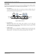
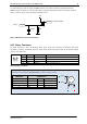
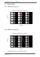
1. BUS STRUCTURE:
The network topology should follow a bus structure as closely as possible. That is, the
connection between each node and the bus itself should be as short as possible. Basically, it
should be short compared to the length of the bus.
c:>
node
1
node
n
- 1
node
n
Host
Slave Slave Slave
CAN
termination
resistor
(120 Ohm)
termination
resistor
(120 Ohm)
}
keep distance as
short as possible
Figure 4.6: CAN bus structure
2. BUS TERMINATION:
Especially for longer busses and/or multiple nodes connected to the bus and/or high
communication speeds, the bus should be properly terminated at both ends. The TMCM-1140
does not integrate any termination resistor. Therefore, 120 Ohm termination resistors at both
ends of the bus have to be added externally.
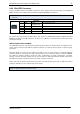
3. NUMBER OF NODES:
The bus transceiver used on the TMCM-1140 units (TJA1050T) supports at least 110 nodes under
optimum conditions. Practically achievable number of nodes per CAN bus highly depends on bus
length (longer bus -> less nodes) and communication speed (higher speed -> less nodes).