
User manual


PD-1140 Hardware Manual (Rev. 1.01 / 2012-JUL-30) 10
www.trinamic.com
4.3.1.2 RS485
For remote control and communication with a host system the TMCM-1140 provides a two wire RS485
bus interface. For proper operation the following items should be taken into account when setting up an
RS485 network:
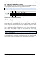
1. BUS STRUCTURE:
The network topology should follow a bus structure as closely as possible. That is, the
connection between each node and the bus itself should be as short as possible. Basically, it
should be short compared to the length of the bus.
c:>
node
1
node
n
- 1
node
n
Host
Slave Slave Slave
RS485
termination
resistor
(120 Ohm)
termination
resistor
(120 Ohm)
}
keep distance as
short as possible
Figure 4.4 Bus structure
2. BUS TERMINATION:
Especially for longer busses and/or multiple nodes connected to the bus and/or high
communication speeds, the bus should be properly terminated at both ends. The TMCM-1140
does not integrate any termination resistor. Therefore, 120 Ohm termination resistors at both
ends of the bus have to be added externally.
3. NUMBER OF NODES:
The RS485 electrical interface standard (EIA-485) allows up to 32 nodes to be connected to a
single bus. The bus transceiver used on the PD-1140 units (SN65HVD3082ED) has just 1/8th of the
standard bus load and allows a maximum of 256 units to be connected to a single RS485 bus.
4. NO FLOATING BUS LINES:
Avoid floating bus lines while neither the host/master nor one of the slaves along the bus line is
transmitting data (all bus nodes switched to receive mode). Floating bus lines may lead to
communication errors. In order to ensure valid signals on the bus it is recommended to use a
resistor network connecting both bus lines to well defined logic levels. In contrast to the
termination resistors this network is normally required just once per bus. Certain RS485 interface
converters available for PCs already include these additional resistors (e.g. USB-2-485).
node
n - 1
node
n
Slave Slave
termination
resistor
(120 Ohm)
+5V
GND
pull-up (1k)
pull-down (1k)
RS485- / RS485B
RS485+ / RS485A
Figure 4.5 Bus lines with resistor network